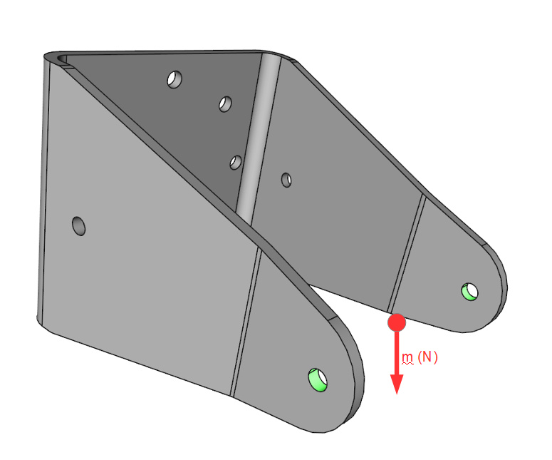
In some of my last projects I needed to simulate the effect of the mass of a part attached to a structure without designing the part itself, because the part itself was out of the scope of the simulation, only the structure that holds the part had to be simulated. In order to do so I used the “Remote Force” boundary condition as shown in the picture below.
The simulation was Static and I just defined the mass of the part in Newtons given in the mass center of the “remote part” and applied to the faces shown in green in the picture above. I don’t know if this is te best approach so as to define a “remote mass” for the case I am mentioning but the aim of this thread is not to discuss this implementation. However, feel free to comment if you think it is not a good implementation, I’m opened to receive critics on my approach!
The aim of this thread is to discuss about the convenience of using the same approach in a dynamic analysis i.e. a shock/impact analysis. Would you recommend me to use this approach in order to define the “remote mass” for an impact analysis? Or would it be better to add a real mass (a sphere, for instance) equivalent to the mass of the part even though not the part itself?
Looking forward to a nice discussion and a deep learning!
Let me tag our “Remote-BC-Expert” and PowerUser @ggiraldo here Maybe he can comment on your project and give you some useful impetus. Also tagging our other FEA experts @BenLewis and @cjquijano here.
I agree with you that this is a good approach for the static analysis, I would do it almost the same way. Possible improvements that I would try:
1- Use only bottom half of hole faces, in order to improve local stress accuracy. Never forget Saint-Venant’s principle.
2- If you want more precise local stress, you can model a dummy body such as a shaft through the holes, and model the physical contact (this requires a non linear statics analysis), then adjust the weight of this body to the correct level, maybe through the density.
About the dynamics case, I think that this approach wouldn’t give the correct results. The reason is that with a remote force condition no additional mass (i.e. inertia) is being modeled, just the load. This would need what is known as a point mass or point element and some contact relations, but this functionality isn’t currently available on the platform.
I totally agree with you on that. However, I have a question, in my previous simulations I applied the weight force in the whole cylinder for a (wrong?) reason: appart from the weight, I had aerodynamical loads (forces and moments) coming from the omitted part also applied to the mass center, so I put it all togehter in a single BC. Would it be a better approach to split it into 2 BC’s one for the wind loads applied to the whole cylinder and another one for the weight applied only in the lower cylinder area?
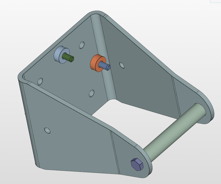
This is something I already did in some previous simulations, actually I did it in the case mentioned in the first post with a single support holding an “invisible” speaker. Below you can see the shaft you mention. In this case, however, I applied the wind loads and the weight to the external face of it instead of playing with the density of it. All the contacts are bonding contacts so as to keep it linear and simple.
Note: I used this simple case in the first post because it is easy to illustrate my approach in it due to its simplicity, just to avoid any confusion from now on.
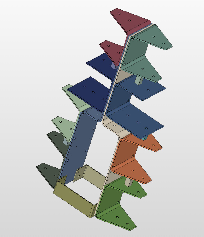
On the other hand, I used the approach mentioned in the first post (omitting the shaft and applying the weight load directly to the whole hole) for a most complicated case of a structure made up of a set of parts that hold 8 speakers (see picture below). In that case, it would turn out to be too complicated to consider 8 shafts + the tightening bolts since without them the assembly already contains 20 parts and I wanted to keep the case simple.
This was what I was looking for when I defined my remote mass as a remote force in my static analyses. Would it be possible to add this functionality in SimScale? I think it wouldn’t be a big effort, would it? It would be extremelly useful for cases like mine, don’t you agree?
Otherwise, I am forced to add the shafts and bolts to the assembly in order to simulate the masses of my speakers, which adds 24 parts (8 shafts + 16 bolts), making the assembly larger and so does the amount of contacts between parts. I thought about implement it this way for a dynamic case in order to account for the weight of the speakers instead of a constant load despite the amount of parts added, what would be your optimal approach in this case (the speaker set structure shown in the last picture)?
You are welcome, it is always nice to discuss over good examples.
I think you don’t need to complicate too much. If you are modelling the cylinder and using bonded contacts it is the same as using the remote conditions on the whole face of the hole, you are only wasting simulation resources because of the higher number of elements that don’t yield relevant information. The modelling of the cylinder would pay off when making a non-linear simulation with physical contacts.
Did you already analyse the results you are getting with your approach? How realistic do they look? Is the area around the whole a critical one? Does it have big gradients/complex stress patterns around the hole, with respect to overall stress levels? How does it compare to a slightly more complex model? How will it change with changes in the load? These are the kinds of questions I always use to improve my models or stop complicating things.
And how did it turn out? Were you able compare the two approaches?
Of course it will be a great addition when it arrives! For case like this one and many others. I think this elements are part of a plan to implement structural elements, which will also include beams and shells. It is a big update so it has taken some time, but let’s hope it comes soon.
The point here, I think, is to first define what information you want to extract from the simulation. I know your focus is on the structure, but what do you need exactly? By dynamic you mean transient, harmonic, modal? Do you need precise stress levels? Vibration frequencies/modes? Harmonic spectrums? The answers to these questions define the modelling approach!
 Maybe he can comment on your project and give you some useful impetus. Also tagging our other FEA experts