Hi @gkondracki,
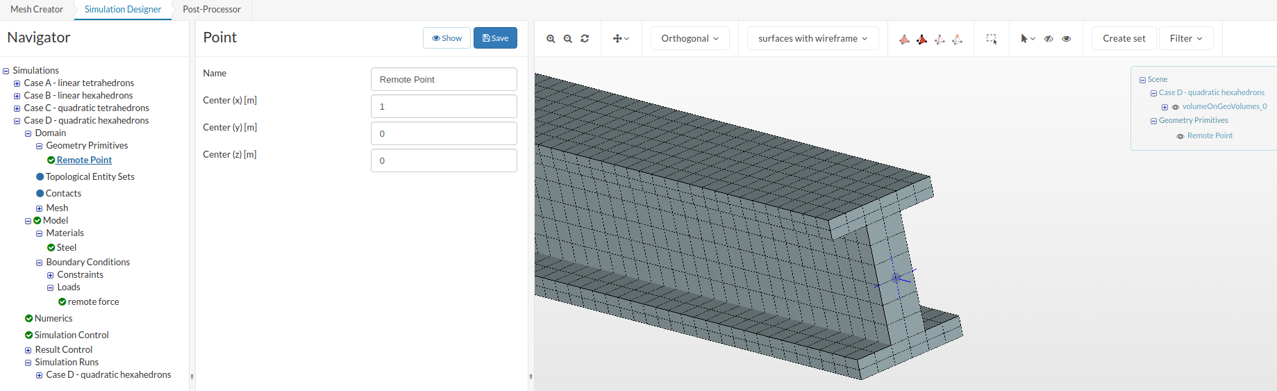
first lets try with the easiest part - visualization of point coordinates. If you see a remote point in a simulation you can visualize its location by creating a geometry primitive of type point:
I guess you read the part about the remote displacement constraint in our documentation. Let me describe the concept of it a little more descriptive with an example.
The basic idea is that for the remote displacement constraint the translational and rotational behavior for a specific point in space is defined (for example “free to rotate around z-axis”). Then this point is connected via “multi-point constraints” to a face or edge of the model (either allowing a deformation of the connected areas or not).
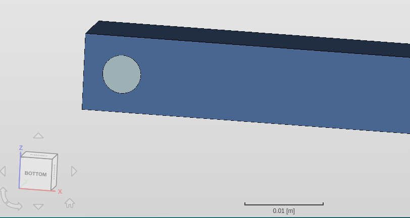
As an example, imagine you want to model a pinned constraint, as seen below without actually needing to model the pin and the contact:
What you should do is:
- choose as remote point the center of the pin
- fix all degrees of freedom but the rotation around the axis of the pin
- assign it to the cylindrical pin surfaces
In a sketch this looks like this (dashed lines represent MPCs), remote point in the COG of the pin:

Be aware that this constraint only works correctly under the assumption of small deformations and rotations (<~5°) .
Resulting displacement compared to a modelization using a modeled pin and sliding contact:
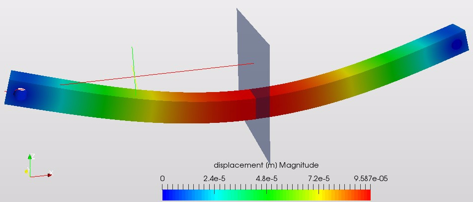
Left: Result using remote constraint Right: Pin modled and sliding contact between pin and bar
You can check out the actual project related to the example above from here: Pinned Bar Example - Remote Displacement vs Sliding Contact by rszoeke | SimScale
I hope this helps understanding the remote constraint a little.
Best,
Richard