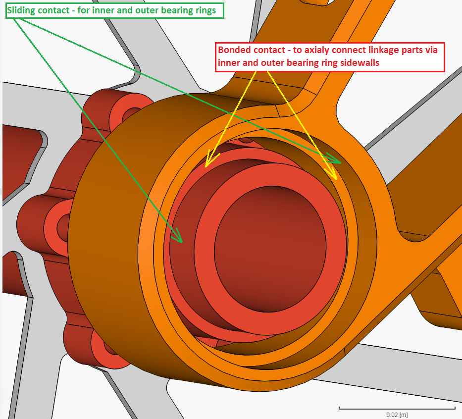
Hello. How is using Bonded and Sliding Contact constraints to mimic ball bearing in linkage assembly reliable?
I’ve been using Sliding Contact between two concentric cylinder surfaces to mimic bearing inner and outer ring rotation between two linkage arms. But I must look out even for lateral and torsional flex of the assembly and I’ve found that Bonded Contact constraint between matching axial faces where ball bearing ring shoulders are to be touching their housing axially, that Bonded Contact used this way leads to some “visually” consistent and trustworthy results.
That’s why I’d like to ask you if this approach is enough to simulate for axial bonds of ball bearing? If it is trustworthy and simulating entire linkage with real ball bearings is useless waste of corehours because it will not lead to much different results?
I’m currently trying to set up dynamic simulation of single ball bearing with 8 balls in order to examine some tilting moments, but I’m still getting some solver dead-ends. I can’t even reproduce the original settings of copied simulation (I don’t want to use symmetry).
tagging @ggiraldo, @cjquijano as well as @BenLewis here who might give you some little tips on how you could optimize your approach. As this is a linear constraint type no large sliding and rotations are allowed in the proximity of a sliding contact - so not sure if that makes sense here.
I have never used this types of constraints to model ball bearing behavior. By analyzing your case, I think that your connection definition is not realistic, specially with the complex loading scenario.
I think you should try a non linear simulation with physical contacts, modelling the bearings.
Hi @jousefm and @ggiraldo,
thank you for your responses. As for using Sliding Contact constraint between two concentric cylinders pivoting around each other I must tell you that SimScale Static-Linear simulation does calculate linkage displacements that are very similiar compared to other tools. By very similiar I mean small variations from 1mm. Even the calculated stress is similiar to Inventor 2012 results. And I’m putting the Sliding Contact between cylinders that are like 8mm apart each other.
I’m now struggling with setting up the constraints and numerics conditions of the ball bearing model. It’s a simple model of ball bearing with 8 balls and retaining cage, and I can’t make it finish successfully in Static Non-Linear simulation. I was getting the “Newton convergence could not be reached. Possible options to prevent that behavior: Update the tangent matrix more often, increase the maximum number of iterations, use automatic timestepping or decrease the timestep.” error, have found that using 25 Newton iterations instead of 15, or using only 0.01s long time-step leads to another obstacle “The solution matrix is not factorizable. This might be caused by an unconstrained rigid body motion or by overconstrained degrees of freedom due to multiple linear relations at at least one node.” so I’m trying different constraint setups.
It’s one simple assembly of 11 parts with 2 Physical Contacts. How would I make SimScale calculate non-linear simulation of an assembly of 5 linkage arms with 10 ball bearings? You would ban me from logging in ever
The original project, that only solved for inner ring rotation, took 200 minutes to finish using Symmetry!
I managed to mix all settings so that simulation actually happened to successfully finish and calculate something.
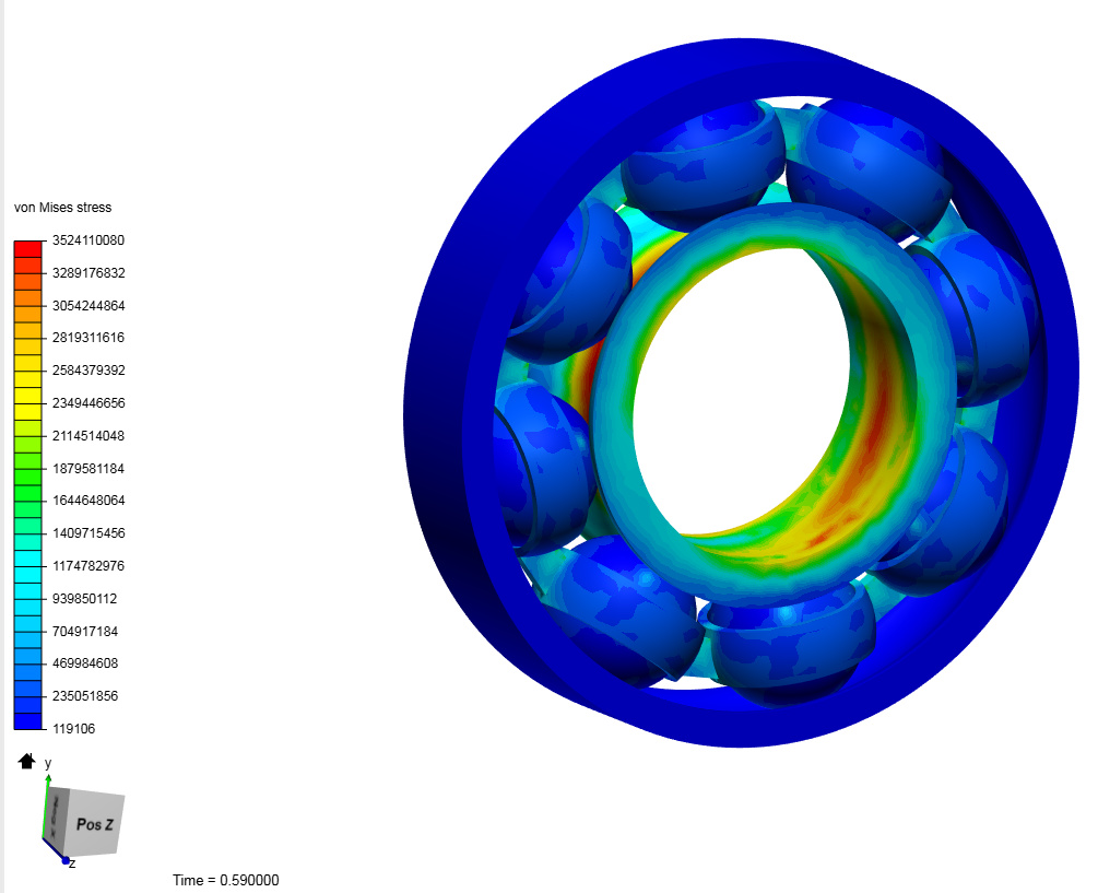
In simple and rather small ball bearing (8 balls) with ball retaining cage (11 solids total), it took as much as cca 180 corehours to calculate 1 second long simulation of a bearing whose inner ring rotates at 7.8Hz, outer ring is fixed, and tilting moment is applied to inner ring inner cylinder. I had to place balls in two separate Physical Contacts for outer and inner raceway, because when single Physical Contact was used it always fails after few minutes of computation. I set a Sliding Contact between balls and retaining cage.
However, actual rotation and displacement of balls and cage is not calculated. They move after the 1st step but keep stationary for the rest of simulation. I copied the Physical Contact settings from @ahmedhussain18 simulation Roller bearing.
One could agree with me that putting real ball-bearings in 4bar linkage assembly with over 8 bearings is pure nonsense. If, very big IF, it ever successfully finished, the increased complexity would take thousands of core-hours.
I will therefore try to approximate the ball bearings by some weirdly shaped bushings.
Congrats on the successful simulation! You could simulate the other scenario by making use of symmetries and if not needed remove the cage as well, just an idea. I will have a look at the settings and see why it does not move nor shows the displacement in the first place.
Hi @jousefm. Yes, removal of the cage would be desired since it’s been my intention to compare a standard bearing with a full-complement bearing (maximum number of balls used instead of cage). Questionable dependency on shaft speed and mounting configuration, tilting moments oscillating in magnitude and direction, …