Question about yPlus Computing at Simscale

Hey guys. I´ve been doing some more half FSAE Car simulations, in order to obtain a reliable Cd to me and my team, because we are going to validate it.

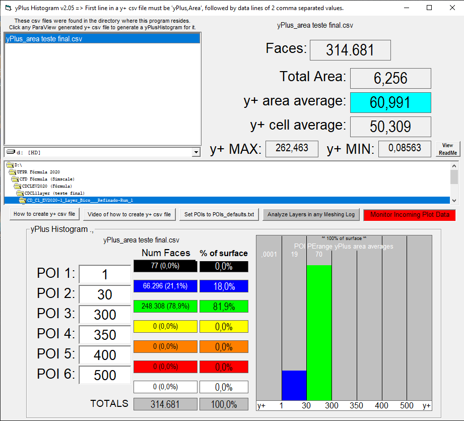
My doubt is about the way that Simscale compute the yPlus. I´m currently trying to achieve a range of 30-300 y+ at all my surfaces in my simulations, and i´m experiencing some weird things about the layer formation. Mainly in some specific faces, at the nose of the car and the front tire. In those surfaces, although the layers are beeing created, the yPlus isn´t reaching 30. My plan used to be increase the size of the first layer in those regions until i didn´t see any region under 30. But it does not matter how much do i increase it (I already did 2 tests by increasing a lot the first cell height), the yPlus just didn´t rise, it only get worse!


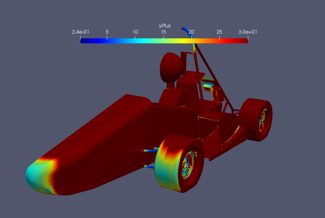
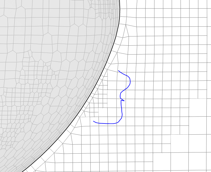
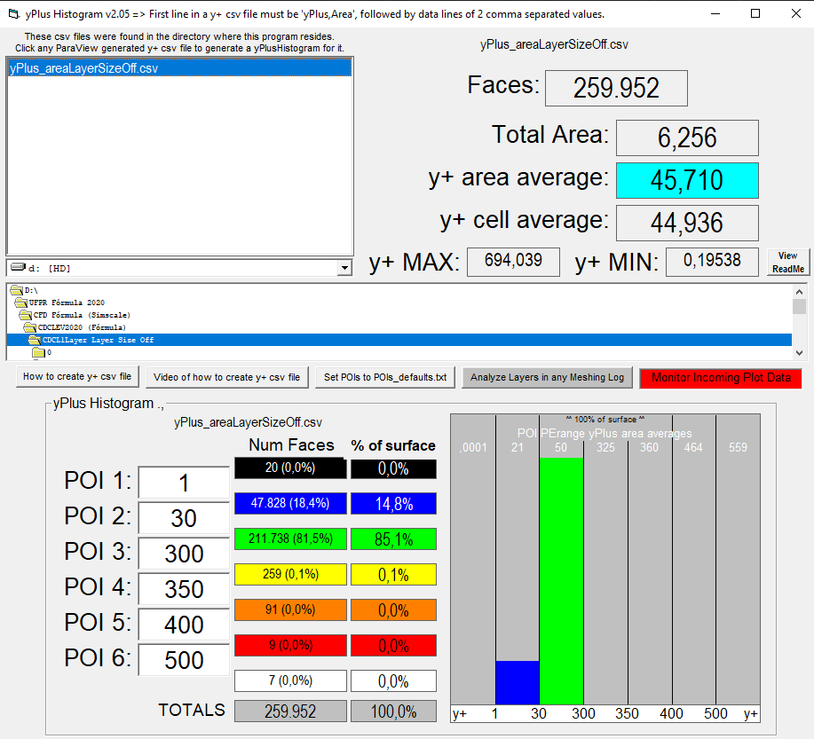
Colored areas are y+<30, visualised using ParaView.

So here is my question, how the Simscale calculate the y+ besides using size of the boundary layer, or in my case, first layer? I´ve read some bibliographies that says it involves Reynolds number and Wall Shear Stress, and it does make sense, because this areas im experiencing problems are the ones where wall shear stress and reynolds are very low because of the low velocity at the stagnation points, making y+ go down.
And this one is the last question: If i´m right about the wall shear stress, and i know that i don´t have any control of it, how do i make this faces go >30, besides incresing the size of the BL?

Here´s the project link https://www.simscale.com/workbench/?pid=4922714590384480106&mi=spec%3A35f219ba-9713-4101-8e99-86f451eaba4d%2Cservice%3ASIMULATION%2Cstrategy%3A166

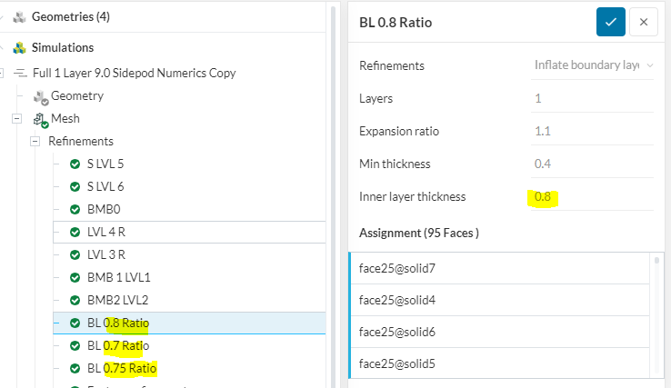
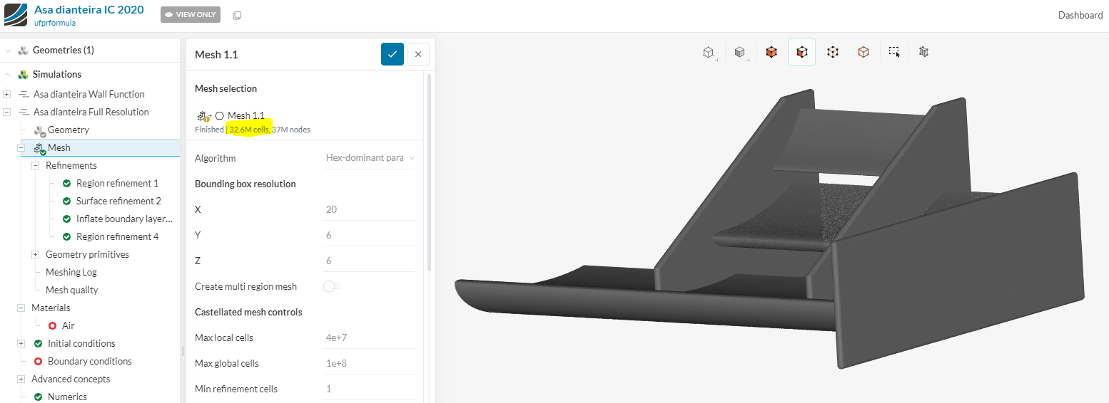
i´m talking about “Mesh Full 1 layer Raiz”, biggest boundary layer cells, simulation “Full 1 Layer 9.0 Sidepod Numerics Copy”.
And “Mesh Full 1 Layer”, smallest boundary layer cells, simulation “Official Run”.

@DaleKramer & @dschroeder discussed this quite extensively in another thread, do you mind jumping in here guys?

Best,

Jousef

1 Like

@ufprformula

Hey, here is some general findings from our testing

Simscale doesnt calculate the Y+ layers. The desired Y+ value should be chosen based on what you are trying to simulate. You are doing the log-law region so 30-300 is correct. The Y+ value can be calculated using THIS calculator. Be aware that the resulting value can be the cell height or cell centroid distance based on the calculator.

You pretty much do have to adjust the BL size. Simscale has two different ways of altering the BL during the layering operation.

  1. What you currently have:

The Layer Size slider changes the BL settings from a relation to the local cell size (Layer size on - as shown in the pic). So if you have for example a level 8 cell size along the geometry surface that shrinks down to a level 9 cell size, the BL will shrink down also at the specified ratio.
image

Here you have given a 0.8 ratio in relation to the local cell size. the other tests you did (0,7 and 0,75) actually made the BL smaller … this is why your results seemed worse.

This can be observed in your nose where the cell size decreases a level and the BL also decreases.

What you should try is the following

Turn Layer Size OFF and set the final thickness to 3.4mm

With layer size off, the BL is in absolute mode and does not change when mesh size decreases

Dan

1 Like

Hey Dan! Really glad to see you jumping here, thank you so much!
I understand what i was doing wrong and right now i´m trying the config “Layer Size Off + 3.4mm 1 layer”, i think it should work. But i still have one more question to ask:
When you say about my other test, i did reduced the ratio because i increased the size of the nose cells, by changing the nose level to 4 instead of 5, that´s the test i was talking about. And the cells were inscresing at the meshing log, i did the comparation between the meshes, but the y+ at the end of the day didnt increase. So, knowing that, can we assume its because of the combination of bad geometry of the nose + layer size on that was causing this?

Yea so if you decreased the surface/ region refinement from 5 to 4 then you are correct the BL would increase in size in relation to the larger cells. I honestly didnt have time look to too deeply into your mesh parameters but if you had, for example, forgotten to change the distance region refinement level as well then this could be a problem as a higher region refinements will override the lower surface refinement.

Since you already have paraview, i highly suggest downloading the Y+ Histogram program from Dale Kramer. It is extremely useful in calculating exactly how many cells are in the desired + range.

His ORSI program is also amazing for analyzing convergence and also for accurate data recording.

It could be this simple. However there are a lot of factors that can effect the Y+ levels. The main one being BL size but snapping conditions and layering settings also can have an effect. Try out the Y+ Histogram as it is extremely helpful.

If you have any more questions dont hesitate to ask

Dan

1 Like

Hey! Thank you to replying so quickly. Actually i´m a big fan of Dale´s program. I use it since i read your big post with him, about a month ago (Thank you so much for that, it helped a lot! Because we are a FSAE team as well and we have sort of the same problems :smile: :smile:). But i decided to not put in this post because i thought some other power user besides you guys might not understand it. Well, just in case if you want to see the results of your mesh, here´s the yPlus Histogram from the last one, and the 3.4mm layer size off. It not solve completely the problem, but was helpfull!

And i still have one more question, Dan. I´ve seen you use a lot of distance region refiment in your simulations. What do you think when you are setting the distance? I´m trying to use it as well but i don´t know wich distance is good enought, or bad enought

good to see you’re using his program… it is super useful i agree. I see on your tests that you still have 18% and 14% Y+ under 30. Normally this is not good at all but i assume this could be because you didnt use a BL on your motor region. Unfortunately the histogram reads the whole geometry so its hard to get an accurate reading of the Y+ for the surfaces that need a BL. Maybe there is a way around this by excluding these geometries from the face extraction in Paraview.

This is a loaded question because it goes into the topic of Quality VS limitations of your sponsorship. I see your meshes are around 4-5 million cells. The upper limit for the 32 core student sponsorship is 20 million. So you definitely have room to increase fineness.

That being said, i generally had the distance region refinement a bit larger then the BL.

For example:

you have a surface refinement of level 8.
your BL is 3.4mm thick.
then i would set the first level of the distance refinement also to level 8 at maybe 5-7mm
then a level 7 at 10mm
then a level 6 at 15

and so on until your are in the range of your cartesian box region refinements which for me would be a level 4 small box around the car and a larger level 3 wake refinement box.

IMPORTANT

ALL of the recommendations that i gave are ENTIRELY dependent on your situation and what your are trying to simulate.

For example
if you want to see the effects of airflow to the rear wing, due to changes in the front wing, then i would increase the overall fineness of the mesh for the front wing and maybe front tires. This could also require a thicker first level distance refinement to help get better resolution. It could also mean adding an even finer cartesian box region around the front wing… its entirely up to you with limitless possibilites.

half car simulations are a great way to get some good initial results and quicker sim turnaround times. However, i am not a big fan of half car simulations for final testing. For me, the most accurate simulation is a full car model with roll, pitch and sideslip angle (yaw)

so a full car sim requires a very efficient use of cells, limiting the region refinements that can be used.

So as a quick overview of what i use for refinements

0.5m^3 level 0 cell size (bounding box setup)

level 8 surfaces for wings/wheels/supsension/contact patch/radiator assembly etc…
level 7 surfaces for body/ endplates/tires etc…

Its really hard to answer because its so situational, but it looks like you are on the right track

Dan

3 Likes

Those regions that are y<30 focused at places that doesn´t affect too much out goals, wich is to see whole aeropackage working together. They are basically the engine, battery, some tubes and other stuff from behind the car. My big problem was with the front tire and the peak of the nose.
And about the quantity of cells: this is our first year working with aerodynamics and CFD, so we are really really new to this and we didn´t want to use too much hours because we planned to use a lot next year with front and rear wings and a new sidepod. So we are afraid to use all of the sponsorship hours before ending all the simulations for nex year . That´s why i´m trying to stay really safe here. Right now i don´t think i have any other questions… But, if you say that full car simulations are that important it may be our next step. Thank you so much to keep on this with me, Dan! It was really helpfull

1 Like

No problem!

If you can verify visually that those regions are causing the low Y+ numbers then that works.

If you are making good progress and contributing to the forum, then im sure you could ask for a core hour extension. Your definitely going about this correctly by testing with lower cell counts however not using enough cells can also cause resolution problems.

There is a time when simulating a full half car is necessary but it is also useful to start even smaller, with just the nose or just the wheel for example. then you can find and fix problems without using many core hours.

I would stay away from the full car simulations unless you are towards the end of your half car goals. It does use a lot of resources and must be setup quite differently.

For a full car sim i was around 18mil cells with the mesh using around 100 core hours and a 2000 iteration sim using about 600 core hours.

Good luck

Dan

1 Like

I would definitely go for that core hour extension! Hahahaha
We are actuallty at the complete end of our half car simulations and aerodynamic devices (a lot of the ideas are from your post with dale so thanks again) And we already did some simulations of just nose+diffuser+sidepod or nose+diffuser+wheels+sidepod+radiador for the design competition.
About that part: “It does use a lot of resources and must be setup quite differently”, why is that? In my head the big difference would be just adding new refinements (what i think it might be the problem), boundary conditions, taking off symmetry, adding another slip and things like that, but none of this are a “setup quite differently”.
Thanks again for the answer!

What i meant by “set up differently” is more of a battle against total cell count and illegal cells. (depending on the complexity of your geometry) For your car it might not be that bad and you wont have to reduce refinement settings.

However when i had my Half car sims around 8-9 million cells, i thought i could just switch easily to half car. NOPE haha.

When you change the model from a non-roll and non-yaw angle geometry to a model with both of those in the domain … problems start to arise with non-orthogonality and illegal cells in general. Just because your half-car sims are meshing doesnt mean the the full car will, even with the same settings.

I had to do quite a few iterations of geometry changes to even get full car geometry to mesh.

Also, a project i am now working on is the difference in results between a geometry with Yaw in the domain or a straight geometry with velocity inlet inducing the yaw effect. I am not sure which will be better.

On a side note … how in the hell did you get a 32.6 million cell mesh through? are you using 32 cores?

Hahahahah. I was thinking i could switch pretty easily, but now you scared me! About the 32.6 million cells… As this is a team account, there are more then one person using it. It was a colleague of mine who try to make a full resolution mesh, but didn´t know how to config the cores and refinements, so it ended up like this ahahahahaha. From now on i will just sign just to you know wich posts are from me.
Mateus

Your project its quite too much for me right now :grin: :grin: :grin:. But i have a little idea what seek from this: know the better way to see/represent lateral acceleration, right? For cornering and etc…

i didnt mean to scare you away from a full car sim. I just wanted to give you a heads up that there could be problems.

Yes the project is more for my own validation, not something you should worry about. Ill post my results in the forum when im done.

So my “personal” opinion is that a full car mesh is better for a few reasons.

  1. Downforce is only needed during a turning situation. Driving straight you want minimum drag, therefore minimum downforce.

  2. Simulating a half car will give you a decent analysis of the expected forces at a desired turn speed. However the flow around the car can be quite different when the model is in a dynamic turning situation.

  • Pitch = nose down / noes up situation = more/ less ground effect on front wing = disturbing force distribution front to rear

  • roll = also disturbing front wing ground effect left to right, as well as light flow effects through the car

  • yaw = larger disturbance of forces through the car

  1. All three together and you get a result that could be 40-50 Newtons less then your straight line results. It all depends on your setup. therefore, when i designed our cars package, all my decision came from full car sims with all three aspects. this allowed for improvements to the aero based on where we actually needed it… in a turning situation.

So this is why half car is good for general design decisions like

  • what wing profiles to use
    -what effect does two elements on the front wing have vs 1 between the tire and chassis
  • is my radiator getting enough air

Full car “in my opinion” is more for

  • fine tuning your somewhat finished package
  • Changing wing AOA’s
    -Changing wing positions

If you have some free reading time Here is my thesis paper on this subject. It might answer some questions and give some guidance.

Dan

1 Like

Hey Dan! I´ve been pretty busy lately in other things at the team and didn´t have the time to come back here and thank you.
You didn´t scared me away from the full car sim, you just made me more careful about it. Hahahahaha!
Unfortnantly i don´t have the knowlege or experience right now to opine about your project… So i´m just going to wait until you post here at the forum.
About the dynamic turning situation, i didn´t have any of this information and this made me think some more about our simulations. This year, as we are almost finishing the simulations, i won´t make any changes. But for next year (we are planning to introduce our first complete aeropackege) i will definitely research about it and take your words as gold information.
Thank you so much for the help!
Mateus