Hello everyone,
I am working on a CFD analysis about a blended wing body. At the moment, I have prepared the mesh with the following parameters:
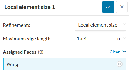
Local element on the wing, since on the previous mesh done, the aspect ratio was very high on these areas.
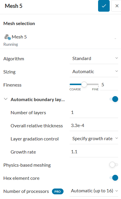
The mesh configuration is the default configuration from SimScale, except the boundary layre, which I have changed in order to reduce the core hours.
And this is the final result:
Can you help me, about what was wrong?
In last case, with a local size equal to 1e-4, I had got a max aspect ratio equal to 19000, and I dont understant the meaning of a enormous aspect ratio.
It’s true the model CAD is a bit small, with max chord equal to 0.15m.
I attach the link of my project:
Hi,
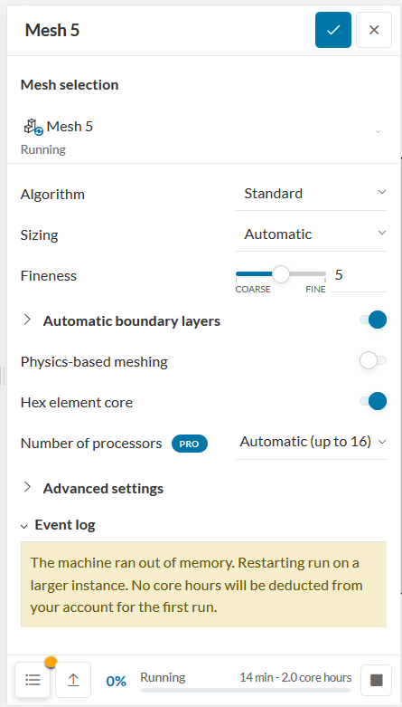
Firstly, on the memory topic: the meshes that you are generating are definitely massive. Just to give you an idea, a 4-core-machine can generate standard meshes with around 15 million cells. In your case, even a 8-core-machine failed with memory issues.
This already gives you an idea of the resulting size of the mesh. In general, this is caused by two issues:
- There are small gaps/small faces in the CAD model. Due to these CAD issues, a lot of very small cells are generated, resulting in a very large mesh
- The applied refinements are too fine, causing the machine to run out of memory
In your mesh, the second option seems to be the case. The refinements on the wing are too fine, causing the cell count to go way up. In short, the approach is to use coarser cells for this refinement.
About the poor mesh quality: the previous meshes were deleted, so there is no way to tell what happened. Based on your description, I believe the issue is likely related to the boundary layer settings. For your information, by defining an “Overall relative thickness” of 3.3e-4, you will obtain a first layer thickness of 3.3e-8 meters, given the current settings (the surface cells are 1e-4). The “Overall relative thickness”, as the name suggests, is relative to the surface cells.
Basically the transition is horrible and the mesh quality is poor. A relative thickness of 0.3 to 0.5 should work better.
Cheers
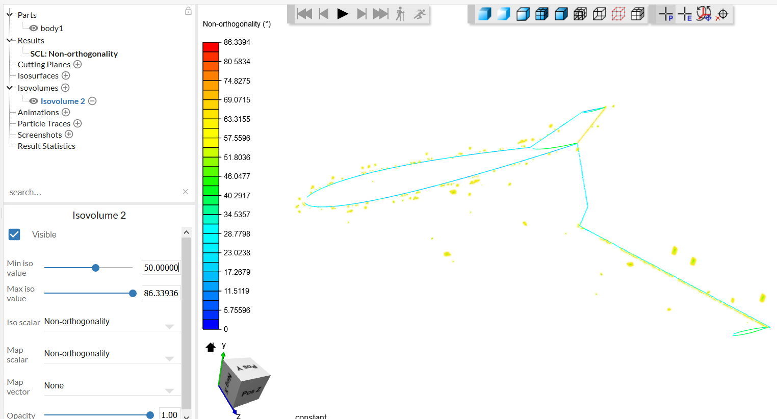
I have been to able to increase the size of my CAD model, and now I have a better mesh, with max aspect ratio of 15.54, its much better than previous.
Although all parameters have improved, the non-orthogonality follows too bad, with a max value of 86.34. In that case, i have used a local size of 0.07.
The highest Non-ortoghonality appear on the trailing edge of the wings:
If the local size is much lower, it could improve the mesh? Or what parameter could suitable to change in order to improve the mesh?