I was able to use the plastic material with the function, but when I apply the same principle for the main model I am getting this error:
The solution matrix is singular. This may be caused by an unconstrained rigid body motion, a physical contact definition with open gap in a nonlinear static analysis or incoherent material parameters
In this example (pipe_03 NL) the pipe is deformed by 1 mm.
This is just a starting point, you will need to add non-linear material properties and the sinusoidal load profile equation. There is probably some scope to speed up the runtime, by, for example, using a larger time step.
Some points to note:
The slave surface area should be as small as possible. This will minimise the runtime and help with convergence.
Set contact nonlinearity resolution to fixed point. This is slower than Newton but more robust.
Set convergence criteria type to absolute.
I don’t have time to go into all the details now but if you have any specific questions please feel free to ask.
Hi @tenshinshoden,
please always add also the project link and try to be a little more specific about the actual error that happened, on which simulation and run.
You should try to give the people who spend their free time trying to help at least the minimal amount of supporting information that would allow them to actually help you.
The next step is to add the sinusoidal load profile. But as it stands now, this simulation will take a very long time to solve with all the time steps you require (up to 600 seconds). I suggest you try to optimise the settings first before attempting the full-length simulation. Here are some things you can try to speed things up:
Increase the load increment size. The larger the load step the fewer the number of steps required to achieve the target load but the greater the chance of failure. Auto time stepping can help in this case.
Use a coarser mesh on the slave surfaces.
Change the contact nonlinearity resolution back to the default type Newton.
Hi @BenLewis ,
yes this exactly the case. The MUMPS solver is struggling to find enough memory, trying to free unused memory to avoid an OOM error. It should not have an effect on the results, just the job might get really slow.
unfortunately it has to be a load, as the engineers in the lab already made dozens of these tests with the pipes
with the same method (specifying loads and the displacement measured until the pipe breaks).
the engineers have some holes in the pipe too and some generated by corrosion.
that would be the next top to put in.
they making the data showing how it influences the load-displacement curve.
It is not clear to me why you need to simulate the full loading history. These simulations do not take into account the fatigue properties of the material so the loading history makes no difference to the final result.
Can you provide some more details on how you plan to use the full load history?
I have updated my example project with a force driven load profile (as opposed to a displacement driven load profile).
[!!!THIS LINK IS NO LONGER AVAILABLE!!!]
Here is an animation of the first 5 seconds.
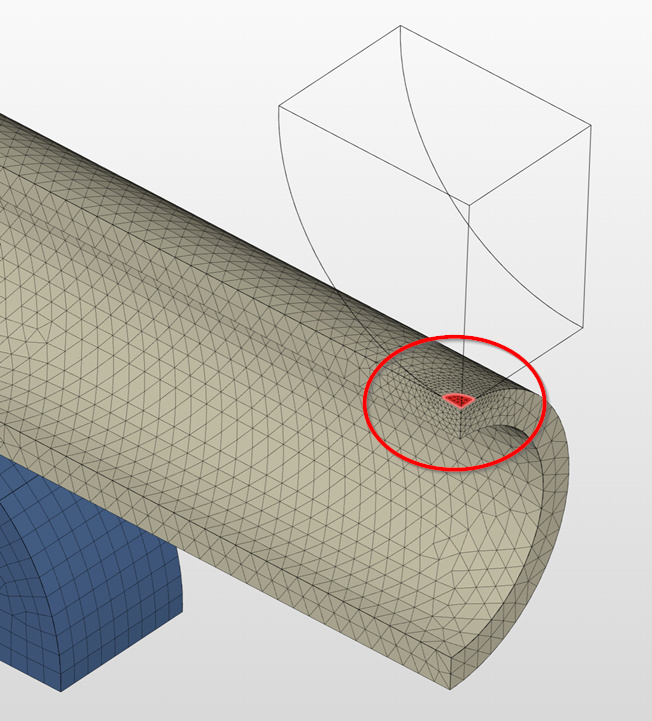
The key to getting this simulation to work was to create a very small indentation in the pipe in the two locations where the round blocks make contact. This eliminates the point contact making it easier to solve.
much appreciated your help, own you a bottle of scotch for your time
Unfortunately these tests been done for a while and I was asked to simulate them.
I was not involved in the load profile set up and the ‘whys’.
I do understand these bending tests do not represent the fatigue properties of the pipes, I guess they wanted to have some more fancy method (and more data) rather than just simple bending until it fails ( or the standard low cycle fatigue load method)
Your Pipe 05 model - Run 4-100 sec looks promising to the final solution, but I think it will not lead to the real deformation because the contact surfaces are much bigger than just those small ‘dots’.
It looks to me -after your hard tries-, that Simscale does not like this 90 deg pipe-pipe contact,
it works nicely for non linear material and displacement boundary condition, could this be a bug?
(also noticed, that the sin function I used has to be +4000 for the initial offset as it starts form 4kN not 4N)
The small indentations are needed to stabilize the initial solution, of course, the contact area will spread as the load increases. The simulation is already set up a allow for this.
You’re right about the load profile equation. I missed the units on the plot in your post. Taking the ‘kN’ into account the load profile should be:
-1000 * SIN(2 * 3.14 / 100 * t) - 10 * t - 4000
The 90-degree pipe contact arrangement is a type of Hertzian Contact. This type of problem is more difficult to solve because of the point contact between the two parts. This is not a bug, it is just the nature of the physics involved.
I have updated my project with another example.
[!!!THIS LINK IS NO LONGER AVAILABLE!!!]
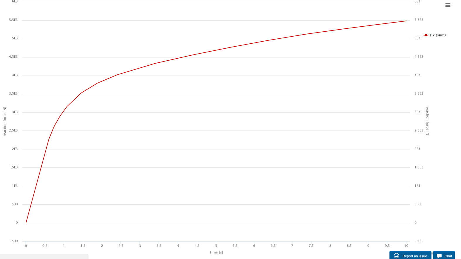
This time I took the deformation to 10 mm. For reference, the pipe outside diameter is about 28 mm.
This has been done with a linearly increasing displacement load. I expect the same thing is possible with the sinusoidal load profile provided above. You just need to decide whether the extra computation time is worth it, given it will make no difference to the final result.
The 4 kN initial load is too abrupt for the simulation to get started. You can modify your load profile equation to ease the load in at the start. For example, the equation below works for me (with auto time stepping enabled).