Hello,
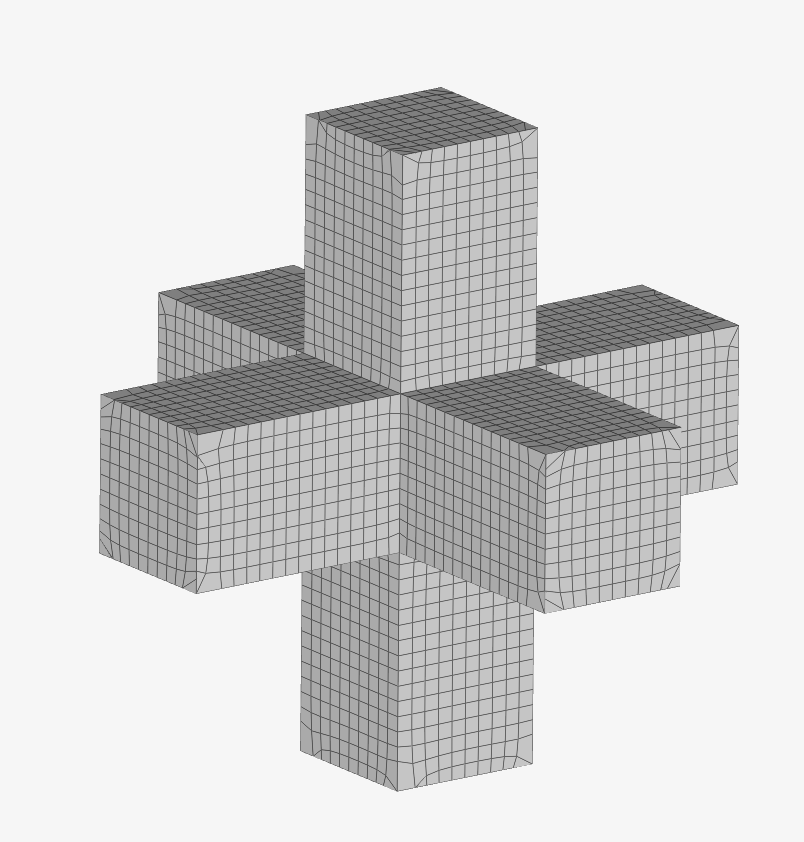
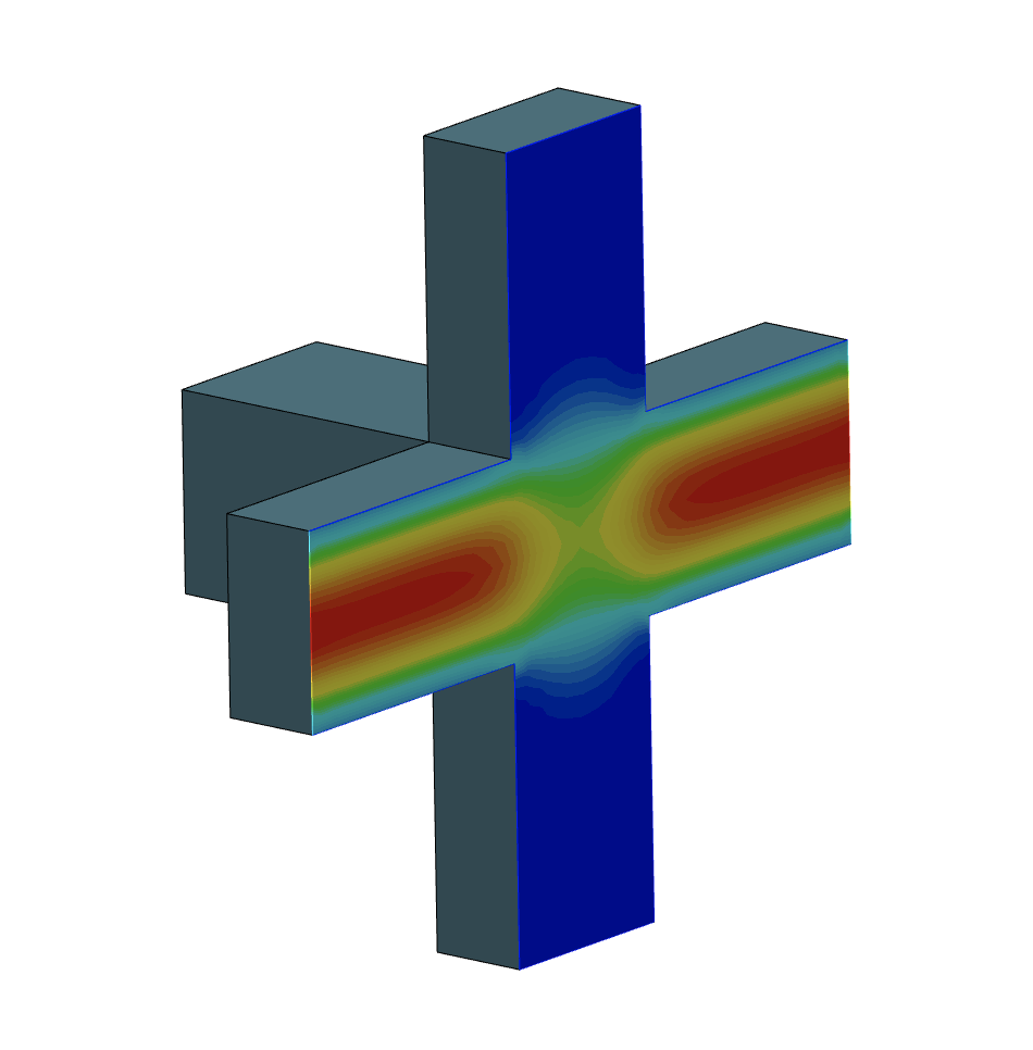
I am trying to run a case where all sides have periodic boundary conditions and flow is driven by a momentum source. This is modeling a unit cell of some porous media. Very low Reynolds number, laminar, incompressible, steady-state. I’m having some difficulty with running cases with more complicated geometries, I’m guessing due to mesh issues. I started with a simple case of some connected rectangular channels, in the image below. Opposing faces of the channels have periodic boundary conditions, so there’s 3 pairs of periodic BCs. I ran the case with a momentum source in 1 direction, and got reasonable results, the velocity magnitude field is below.
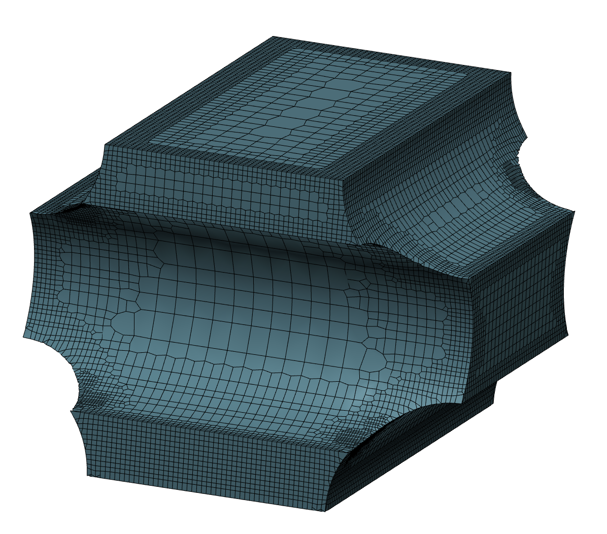
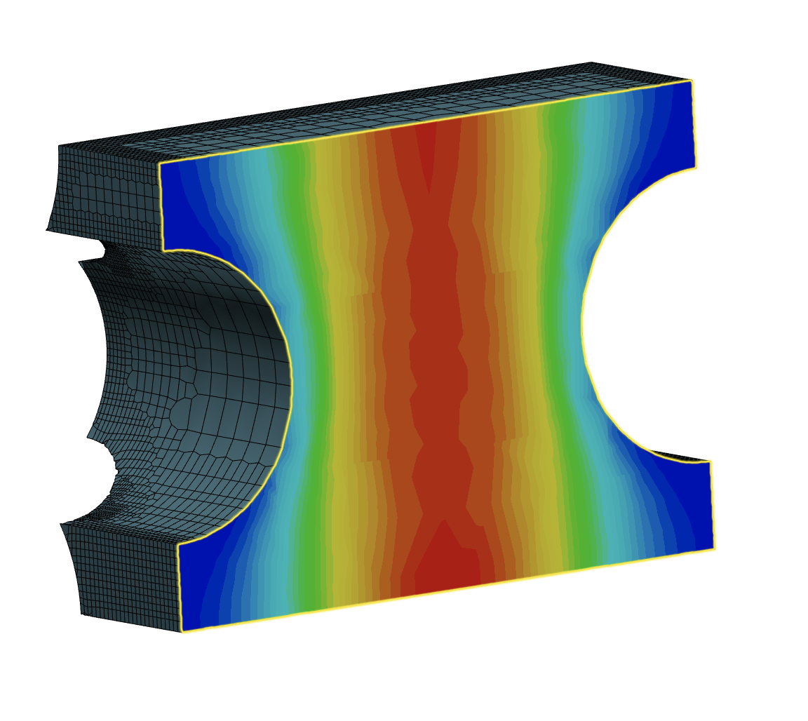
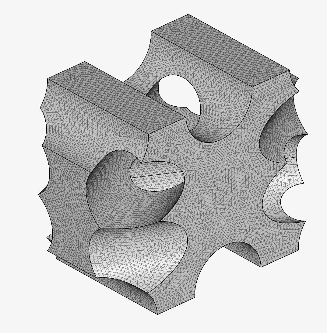
Now when I go to a more complicated geometry, the case fails. These geometries still have matching faces on opposing sides of the CAD file, but it seems that mesh cells don’t line up as well on corresponding faces. I had hoped the cyclic AMI boundary condition would take care of this. I tried hex and tet meshes with different degrees of fineness. The cases do not run at all, they say “case was prepared successfully”, then it fails, and there is no error log. Would appreciate any recommendations or advice for how to proceed with meshing or troubleshooting this issue. Thanks!
Do post your project link so we can check out the project itself.
With regards to your most complex run, from what I can see the issues lies with the meshing algorithm. Currently, OpenFOAM does not seem to like the tet-mesher. Try meshing it with the hex mesher as you have so far done and then simulate again. It should at least run.
Thanks for the reply, appreciate your help. Yes, sorry, forgot the project link. See below:
I re-tried the hex mesher and simulated again. The case still does not run, generates no results or solver log, but I get this error in the SimScale Event Log:
Incorrect definition of patch type for cyclic/periodic boundaries.
After looking at the page below, it seems this is telling me my faces don’t have translational periodicity. So either they (1) do not have the same shape, (2) are not parallel, or (3) are not offset by a vector. I ensured my CAD file had these properties, but I will go back and check again in case I missed something silly. Could I be missing something else? Would partitioning to different processors cause any issues?
Apologies for the slow reply, I missed your earlier reply.
I assume your CAD is correct as you did manage to run successful runs prior to this complex shape.
So far, I’m not exactly sure why the solver is reading the patches incorrectly. Processor partitioning should not affect the simulation, but you can try to increase it to 8 and see what happens or try different decomposition algos.
There could be a definition issue with the mesh as the meshing algo does layering instead of mesh growing onto the geometry surface, hence the definition applied might produce an error due to this. Another try would be to increase the fineness and if that doesn’t work, move on to the parametric mesher where you can set a feature refinement to reduce the jaggedness of the edges that may be causing the faces to not match.
Still having issues after playing around with meshing and processor settings. Is there a way to access the error messages when a case fails? There is no solver log, and so all I have to work with is:
Job was prepared successfully.
Incorrect definition of patch type for cyclic/periodic boundaries.
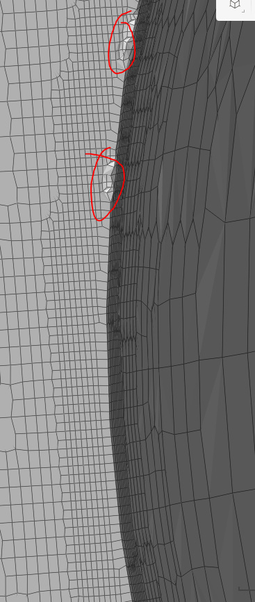
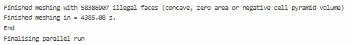
Your mesh is broken. Looking at meshing log you can see an absurd amount of illegal cells. Did you old coarse mesh have the same issues? This illegal cell count will break the simulation and we need to resolve it first before going back to BC definitions.
Is your geometrey watertight? Are best CAD practices maintained when creating said geometry? Try using STEP or STL file format. Remesh using the hex parametric settings and have a relatively high level of feature refinement at distance 0m rather than straight up using a very fine automatic mesh. You will save time both in meshing and in simulation.
Yes instant failures or improper definitions of BCs produce no solver log. You would likely see the same thing if you were looking at an OpenFOAM terminal.
Hi @Get_Barried
Thanks again for the reply. You are correct, the mesh was very bad as I was playing around with different meshing parameters. I was able to (almost) get things working by switching to the STEP file format for importing. Still having trouble getting the mesh to work out on one of the face pairs. I found that meshing on my local machine with cfmesh was quite straightforward and gave a good quality hex mesh. Thank you again for your help with this!