Hi, I’m working on a thermal simulation of the PCB that I exported from FreeCAD using a .step file. When I try to generate the mesh something goes wrong, and in the Event Log is written that “The mesh could not be generated. Increasing the mesh fineness or adding local refinements to geometrical details potentially fixes this issue. Please contact our support for further assistance”. However when I use very coarse fineness there is also a green message “Mesh computation succeeded”, but it’s not true so I am a little bit confused. I tried to change various parameters but the mesh generation always fails.
This is the link to my project: https://www.simscale.com/workbench/?pid=4422527629738570460&mi=spec%3A3d05b7ad-eec4-4859-a163-2ad2a718b824%2Cservice%3ASIMULATION%2Cstrategy%3A1
Can you help me?
Thank you in advance!
Hi @crocioni_giuli!
I would assume that the components are way too thin to generate a proper mesh. Additionally you have overlapping parts (at least that is what it looks like to me) - CFD Squad, could you see if you find any problems in particular in his geometry? That would be awesome! Also tagging our CAD guru @yosukegb4 here who finds geometry issues quite fast 
Cheers and thanks!
Jousef
3 Likes
Hi @crocioni_giuli,
Yup, agree with Jousef. Your geometry has many excessive details and several errors. You will need to simplify and fix the geometry.
Ideally, do you should not have any shell elements in the geometry. They should all be solids. It doesn’t matter right now what the meshing log shows, your geometry is not ready for meshing let alone simulation.
Cheers.
Regards,
Barry
3 Likes
Hi @crocioni_giuli ,
I checked your geometry and I’m agree with @Get_Barried and @jousefm.
Please modify your geometry so that the geometry consists only of closed surfaces.
Regards,
Yosuke
1 Like
Thank you!
How can I modify the geometry? Can I do it directly in my Simscale project? I’m new and I don’t really know how to do it. @yosukegb4 @Get_Barried
Hi @crocioni_giuli!
You would have to do this in a CAD program of your choice, unfortunately this is not possible on SimScale.
Let us know if you need any further assistance.
Jousef
1 Like
Hi @crocioni_giuli ,
A geometry for meshing should be a solid or closed (poly-)surfaces.
I checked your geometry again as shown below.
On your CAD software (not on SimScale website), modify objects those are not good for meshing.
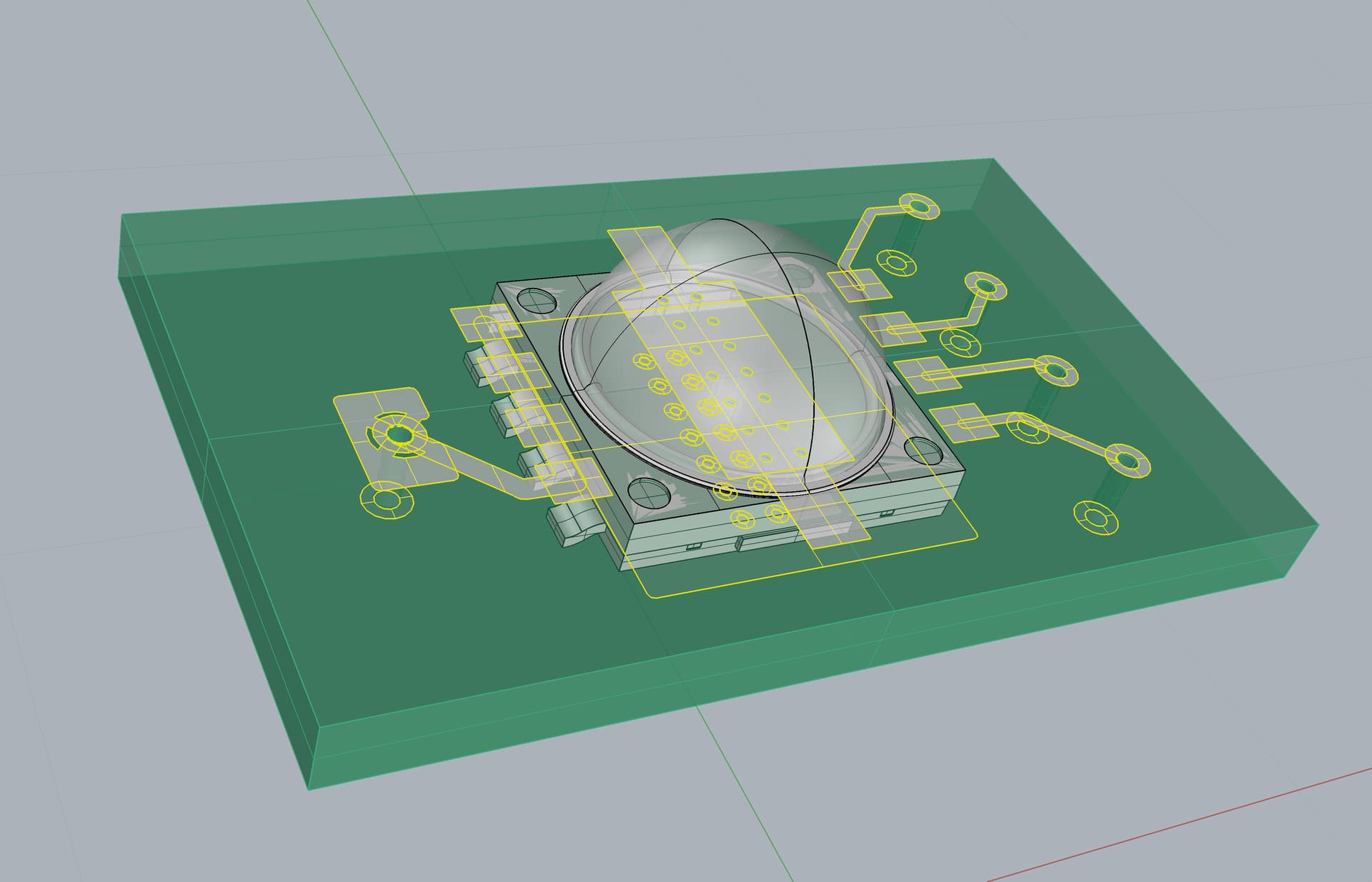
1. Solid or closed poly-surfaces : fine
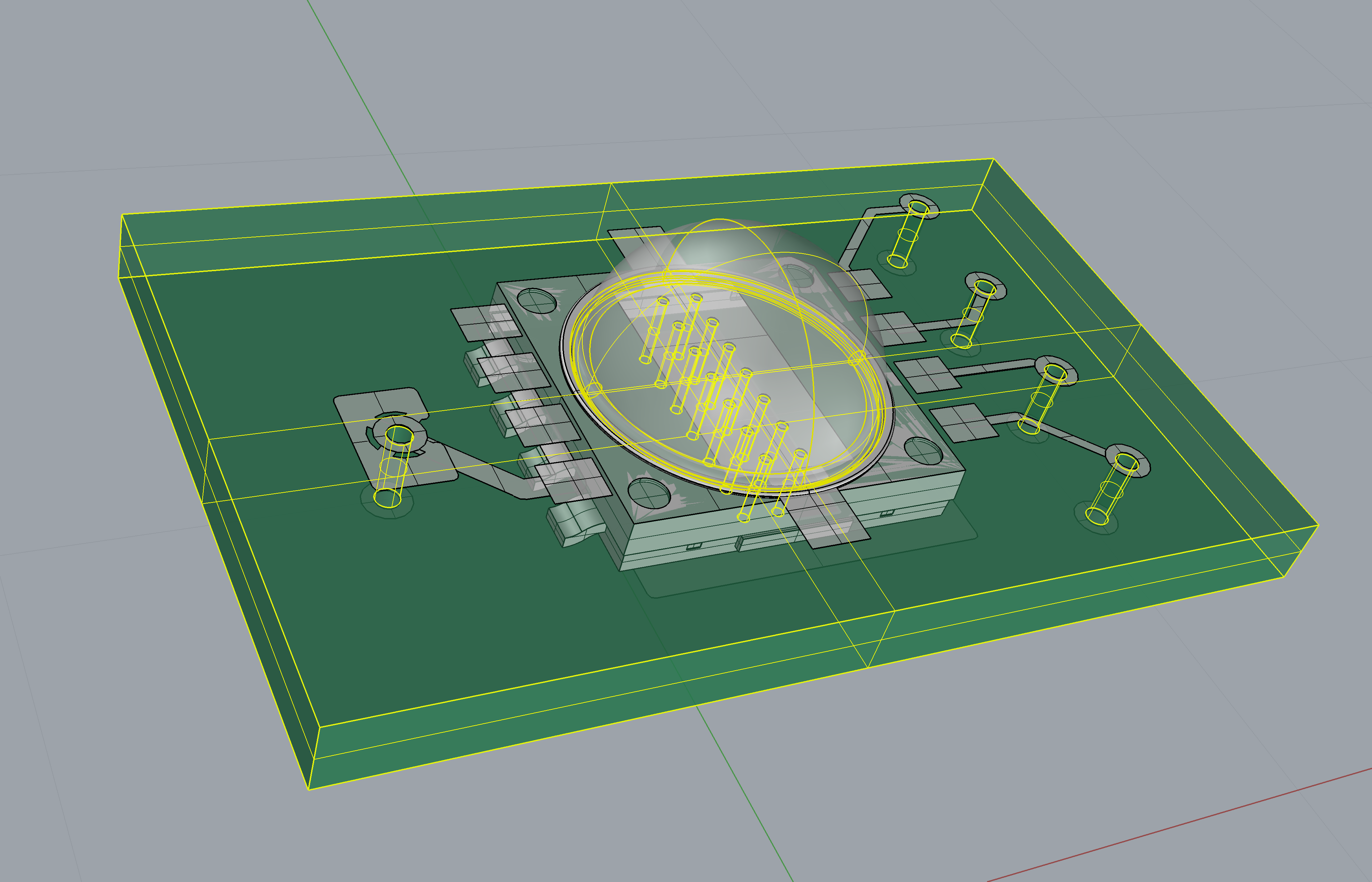
The objects that edges are colored in yellow in the picture below are fine for meshing.
2. Too many duplicated surfaces for a solid or a closed poly-surfaces : not good
The objects (chip model?) that edges are colored in yellow in the picture below consists from too many duplicated surfaces for one solid or closed poly-surfaces. These are not good for meshing. It must be configured with the necessary and sufficient surfaces.
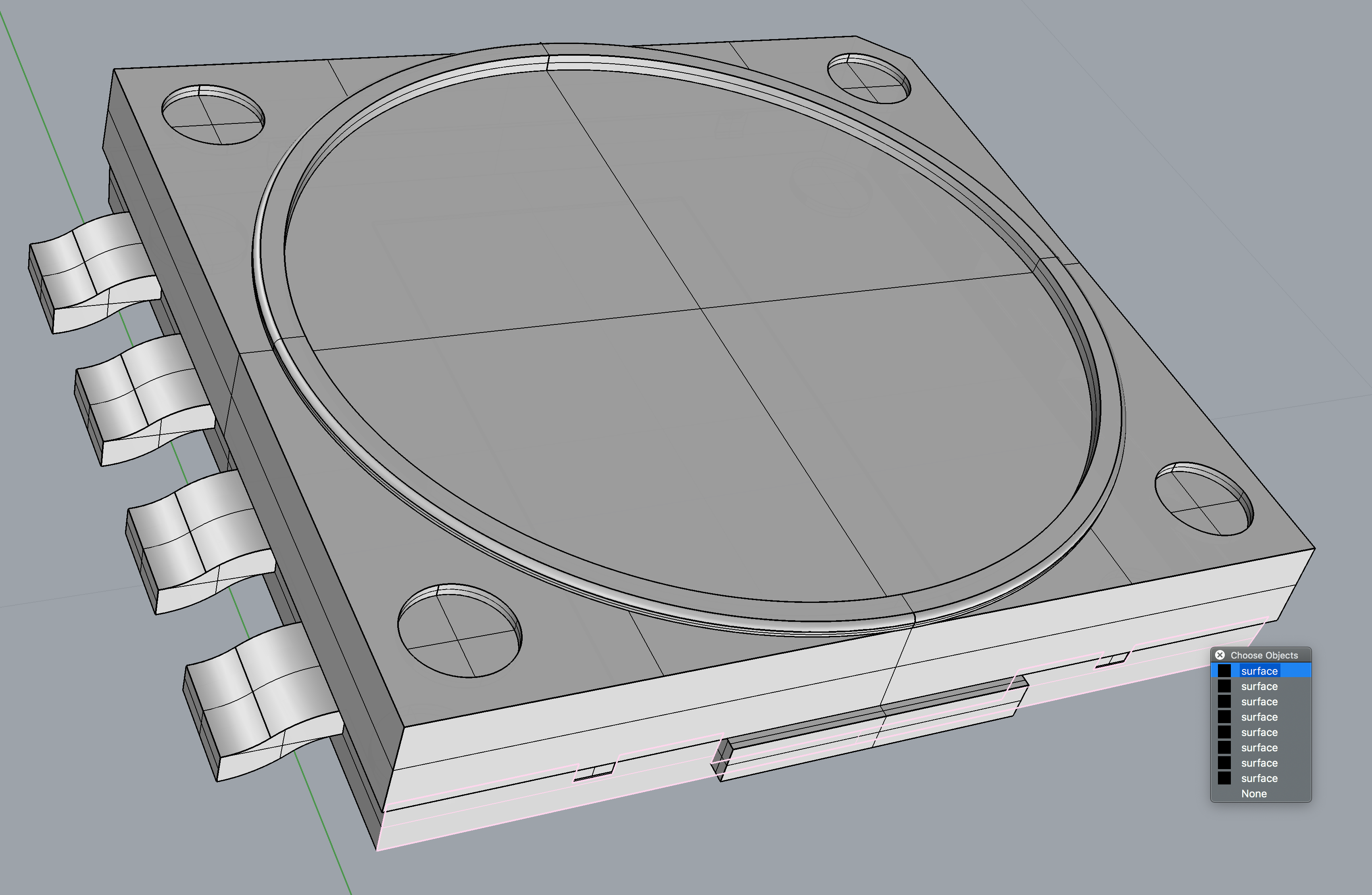
3. Surfaces without any volumes : not good
The objects (circuit models?) have no volume. Not only are they not affected in mesh creation, they also cause errors.
If your simulation model requires them, you need to add thicknesses to the surfaces to make them solid objects.
Else if you don’t need them for your simulation, just delete them.
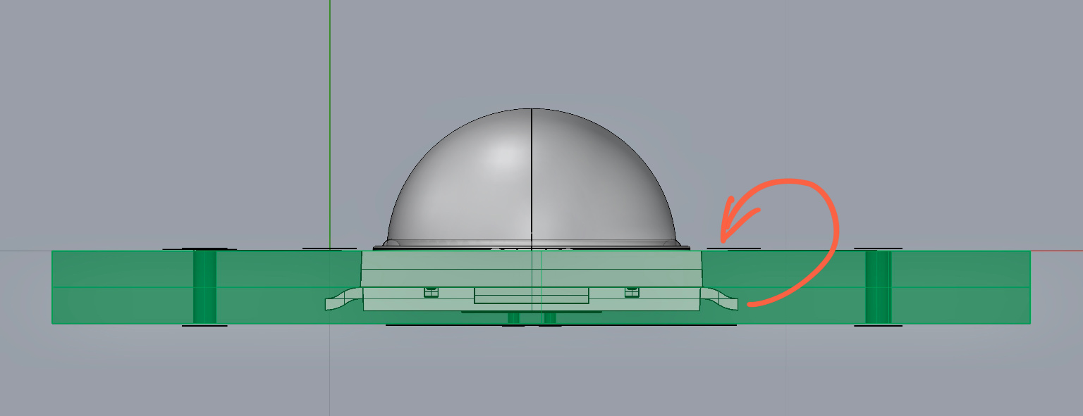
4. Chip and Sensor(?) Position seems wrong : optional
The chip and sensor(?) models seem to be buried in the board.
If their positions are not correct, modify them.
Best,
Yosuke
5 Likes
Thank you so much for the tips! @yosukegb4 They were really useful.
I modified the circuit models adding volume, and I moved the chip (LED) in the correct position.
Regarding the second point of your answer (too many duplicated surfaces): I don’t need that part for the thermal simulation, but it would be nice to have it in the drawing (only for an aesthetic reason).
Is it possible to do the mesh and the thermal simulation only in some selected parts of the drawing? I couldn’t find the option in the online tool.