Hello everyone. We are a F1 in Schools team from Mexico and we have recently won our pass to the World championship. Our objective is to create a small car (20 cm) that runs a 20m straight track under 1 second, therefore we like to reduce our drag to the minimum possible. For the national competitions we have run some simulations, but we don’t know if they’re correctly set. We would like to learn to simulate the effect of rotating wheels. Can anyone help us with a tutorial for this? It would be very helpful if anyone can check the simulation settings in general since we don’t really know if they’re ok. Also, can someone tell us if this simulation settings can get us the most accurrate results?
This looks very interesting! I am from Mexico myself so this is quite exciting for me. I look forward to seeing how it develops! My only advice right now is for you to break down your simulations into different projects. It seems like you are simulating completely different concepts in one big project. Instead I recommend you to make a project that centers on the wheels, another one that takes care of the airfoil (ala) and another one that focuses on the cars. What is the area of interest regarding the wheel? Structural? Aerodynamic?
Nice project. I hope to see a picture of the model your winning model.
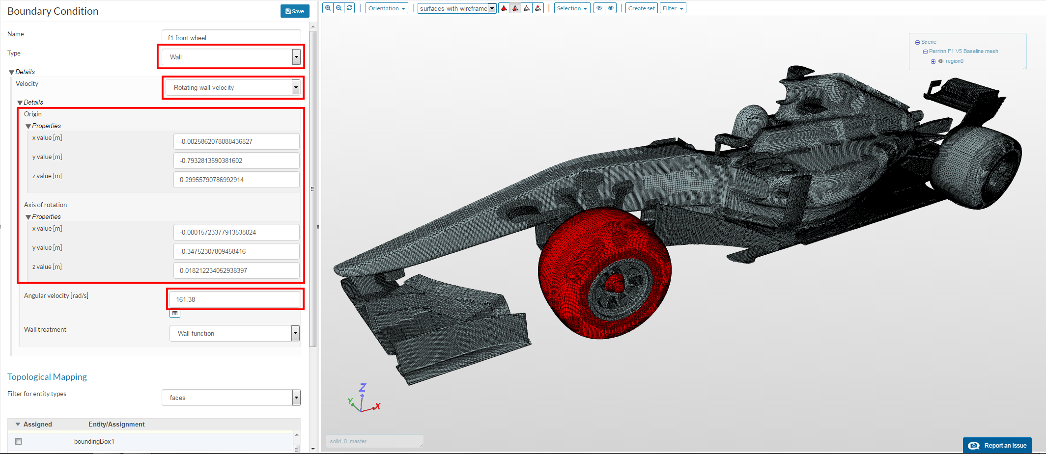
Regarding wheels, as you have axial symmetry, you only need to impose a rotating wall boundary condition.
First you have to determine the axis of the wheel with one point and one vector. Then just specify angular speed (omega = velocity/radius). Right hand rule applies for rotation.
@oscarcorripio You are from México too? that’s amazing where are you from?, we made all of the simulations in the same projects to aid simplicity and ease of configuration,juat duplicating sim settings and defining a new model, we will however create projects for different parts of the car as you advice, regarding the wheel we are leaned more towards aerodynamic around the rotating body, maybe later we can make an structural analysis.
Thanks very much @pfernandez we are looking forward to have your help with our project, when applying the rotational boundary condition do we have to select every face that composes the wheel? and also do we have to apply a different boundary condition to each wheel? (front and rear)
I am originally from Morelia but I live in Boston, anyways you should apply the rotational velocity to all the faces that are rotating at the same speed and that share a common axis of rotation. Given that the front and the rear do not share the same axis you would need separate BCs.
In your case you should assign to the boundary all the faces that compose the cylinder/wheel. In the picture above I just selected the faces that have axial symmetry by revolution.
And yes, each wheel will have its own rotation axis, so you will have to put each set of wheels on its own boundary. Although it is possible for the two front wheels or the two rear wheels to share a common axis if they have no camber nor toe-in.
Following @pfernandez’s reply, you might also want to include a proper contact patch modelling technique. Use a step extruded from the patch to the moving ground in order to preserve cell quality. My colleague in Volkswagen and I have recently tested the effect of contact patch modelling on a coupe, drag force was only 0.5% different from mega cell-count LES ( which was in excellent agreement with wind tunnel testing on a moving ground). Without the step though, drag was 1.7% higher.
To get the center and axis you can use the measure tool in you CAD software. Use te tool to get the center of the circle defining the inner part of the rim; that can be your center. Then, do the same with the external part of the rim; your axis will then be the vector joining those two points. The exact process will depend on your software.