This is probably a rookie question but currently I’m attempting one of the “Solve it with SimScale” projects titled “Validating Turbulent flow around City Blocks” and am having trouble setting up the Boundary Condition for Wind to flow from one side of the set of buildings to the other end from some point away from the buildings.
I have looked at another user (Akrem) simulation of “Aerodynamics Analysis of an Isolated Building” but am unable to mimic the Boundary Condition settings to produce a similar flow type.
For reference here is the public link of the project:
Thanks for the wonderful help again. I did manage to create a bounding box and run my simulation. At the moment everything is running well and I have gotten my first set of results.
Thanks plenty for the prompt and informative help! Couldn’t have done this without it.
Sorry for reviving this thread again but I felt like making a new one would be less appropriate.
Ran into another issue where with a new but similar geometry (Case1H), I am unable to mesh properly and it only produces a single block out of the 9 blocks along with the bounding box not meshing as well. Been trying at this for a whole day but am unable to find a solution.
Hi, @Get_Barried, Is there a new project for this? I opened your original link but there is only mesh for case0H. That said from what you describe above I suspect the material point is inside the block, not the bounding box… but pop a link up and I can look for you. Also, I would want a much larger bounding box than you have.
Hi @1318980! Thanks for chiming in! The link should be the same put i’ll post it here for your reference.
I did a mesh but i deleted it off as I couldn’t produce what I wanted. I’ll do a quick mesh now to see if the problem replicates itself so you can have a better understanding of the issue I’m facing.
Regarding the material point, I believe I did do the first mesh with the material point within the box as well, but it seems logical that it should be outside the bounding box now that I think about, so I will try and see if adjusting it helps.
About the bounding box in this case I wanted didn’t want something too big as I don’t have a gauge on how long the set number of nodes will take to compute, so started reasonably small to familiarize myself with the ins and outs of SimScale. That being said, a bigger bounding box would be better because of better computational accuracy or something to do with the geometry?
Thanks again for the input! Really appreciate all the help.
Just to clarify here the point should be inside the bounding box but outside the blocks.
to start with a small mesh it would be better to make the bounding box bigger with the same number of cells, as opposed to making the box smaller. I think a region refinement around the blocks or a surface refinement on the block would keep the geometrical accuracy.
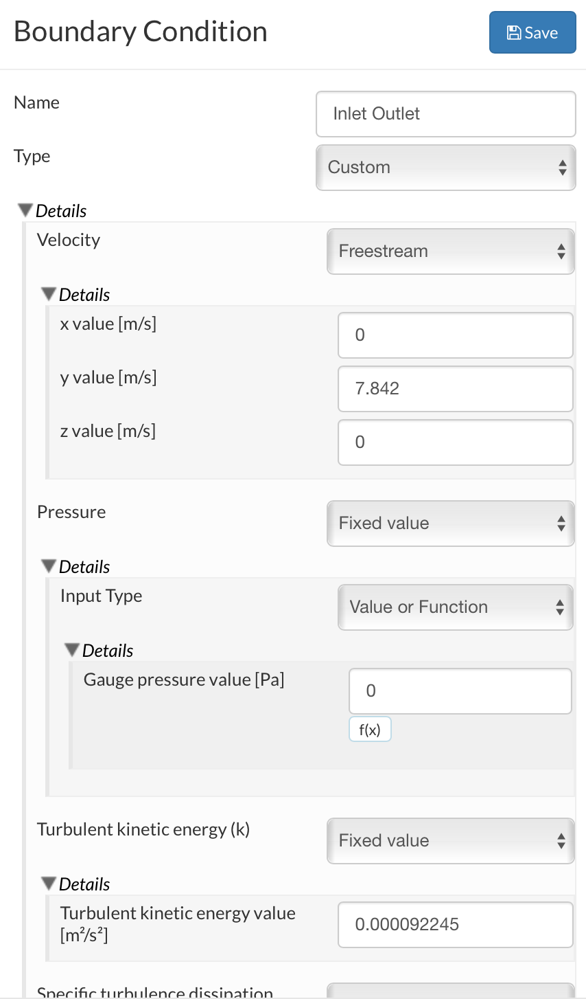
Oh and another thing, if you are interested in changing the wind angle you might want to consider inlet - outlet boundaries. Let me know if you need to do this and I’ll explain more.
Hmm yes I think that the mesh did require some refinement. I will look into it. Great input!
Yes I will require different wind angles as the eventual plan after nailing this project would be analysing flow along larger and more complex buildings with different wind conditions. I’m all ears to learn about how to do this!
I have also just done the “failed” mesh and it should be showing up.
(you could also use the inlet-outlet instead of freestream)
Where we can change the wind speed and angle via the components of velocity, the flow will act as a velocity inlet with defined inputs but will act as a zero gradient outlet where it exits… Docs here
I have used this in the past to vary the angle of attack for aerofoils. This sometimes needs a bit of experimentation and its good to set up traditionally and then compare the results to make sure the setting is correct (there are a lot of options)
Well well, it seems like I did leave the material point inside one of the blocks, hence causing this issue. Thanks Darren, not sure what I could have done without your input!
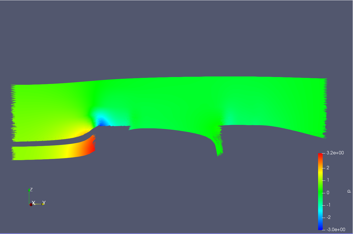
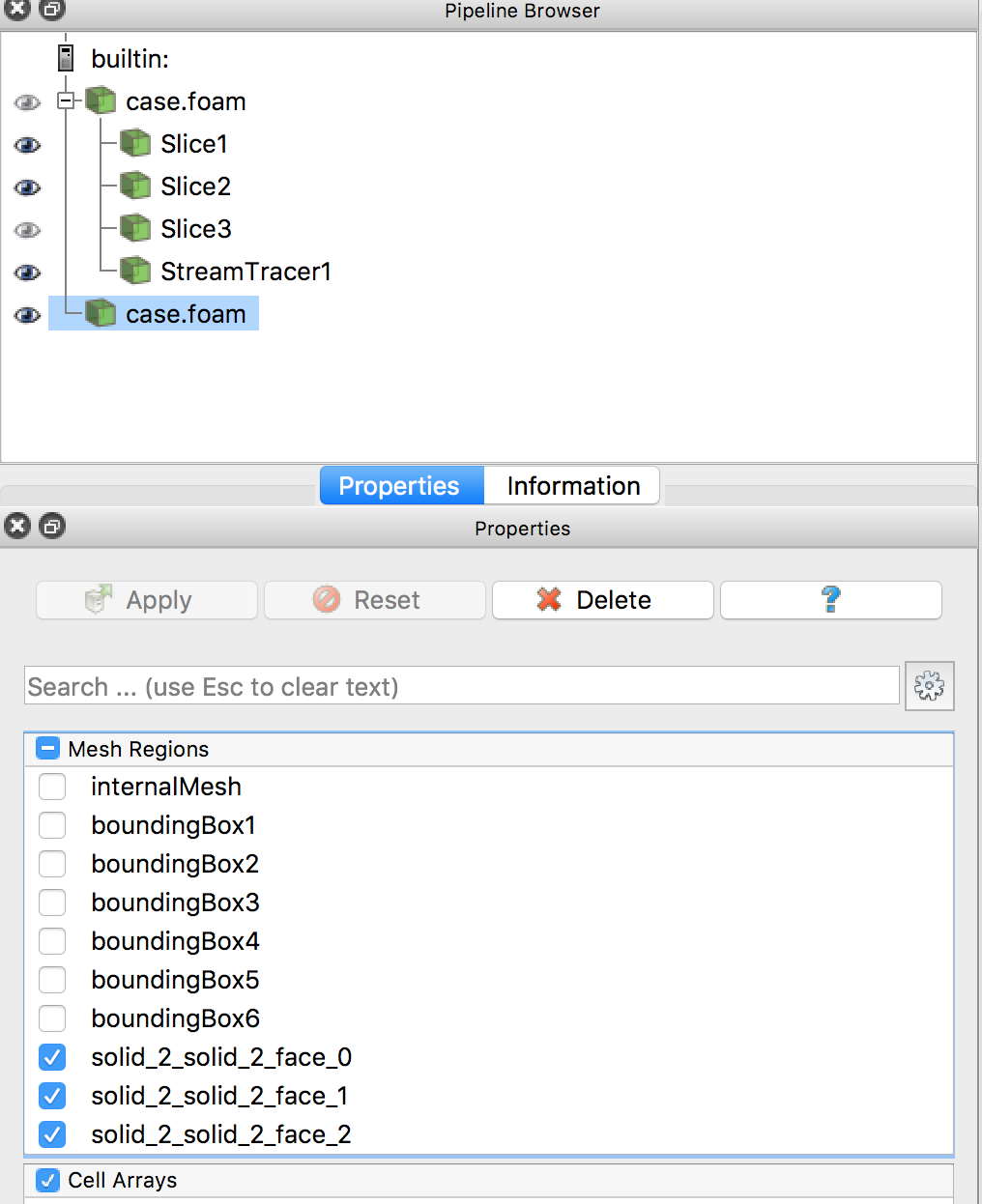
With that being said, my next issue now is just the post-processing. Specifically in ParaView where I’m trying to form streamlines of velocity flow. I did manage to do it but the physical render of the blocks and floor just don’t show up. Posted a screenshot here that pretty much explains:
As you can see this is the middle of case0H where there are just 2 boxes interrupting the flow in the positive Y-axis. Not sure how to get the model of the boxes to show up.