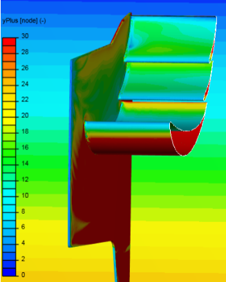
No really correct, any color with green to blue on this plot is <20 (~yellow to red is >20):
.
.
Just worry about getting as much as you can >20, that will be hard enough to do let alone >30
ok thats what ill do for the next mesh runs then Thanks!
Quick check of my method. If i increase the Y+ min value to 80 and keep my 1.3 expansion ratio, then the resultant last layer thickness has a ratio of 1.49. this means the third layer will be LARGER then the neighboring region cell size. If i decrease the region refinement level from 9 to 8 i get a better transition of cells with a ratio of 0.74
Level 9 (0.001953m) final thickness ratio calculation
0.001953m * X = 0.002916m
0.002916m /0.001953m = X
X = 1.49
| Inflate boundary layer settings - layer calculation | Y+ Value | |
|---|---|---|
| Layers | 3 | |
| 1st | 0.001726 | Y+ = 80 |
| 2nd | 0.0022438 | |
| 3rd | 0.002916 | |
| Overall thickness | 0.006886 | Y+ = 320 |
| Expansion ratio | 1.3 | |
| Min thickness | 0.001m | |
| Final layer thickness (RATIO) | ||
| Relative | 1.49 | |
| Absolute | 0.002916 |
Level 8 (0.00390625m) final thickness ratio calculation
0.00390625m * X = 0.002916m
0.002916m /0.00390625m = X
X = 0.74
Would you recommend this or decreasing the expansion ratio so that it will be below 1?
Level 9 cell size = 0.001953m
Expansion ratio at 1.05 = 3rd layer size of 0.001957 . This is 0.000004m larger then level 9 cell size
Expansion ration at 1.04 = 3rd layer size of 0.001866- This is 0.000087m smaller then level 9 cell size
These settings have a upper limit Y+ of 250
My only reason not wanting to have such a small expansion ratio is that the overall thickness of the boundary layer is decreased. I would rather have the BL cells encapsulate as much of the 30-300 range as possible
Also, since I am going through the same process as you on my CyberTruck project right now, I can save you some more grief…
I am trying to layer the treads of my tires and they have only ~8mm gap between knobs…
This makes it extremely hard to do at high yPlus (>20)…
You will have the same problem with increasing yPlus in the gaps between your wings (but not so severe)…
I just spent a whole day trying to get rid of a ‘fineness meshing error’ when I tried increasing yPlus on the tread knobs…
Solution to the ‘fine error’ was to live with just a single layer on knobs and I kept reducing the thickness of that single layer until the ‘fine error’ disappeared and a mesh was finally generated…
Here is a link to the ‘fine error’ mesh and the next sim has the mesh that finally worked, now i am trying to run a sim on it…
This is just a headsup message for you ![]()
thanks that helps a lot. Ill keep this in mind if i run into this problem. I guess ill try both methods. Reducing to level 8 region would help with cell count so ill start with that one
As i assumed the level 8 region refinement reduced the surface refinements also to level 8. Is there some setting im missing that is always causing this? The only way so far to get different surface refinement levels is if there is a feature refinement in the mesh as well
At level 8 you will never resolve anything less than 3.9 mm in your geometry… (my Geometry does not have any faces <4mm so it works for me…)
Those 0.5mm TEs you have really make you have a lot more cells… Even if you could get them to 1mm, it would help a bunch…
If you mesh a CAD file that has finer features than your max level refinement size, then be prepared for some weird meshing edges and jaggies and Snappy ‘guesses’ where to put the meshes surface faces…
i guess my ideal mesh could have a level 9 surface refinement with a level 8 region refinement. It seems that i am not allowed to do this.
I guess your method of changing the TEs is meant to have the smallest geometry size be driving the surface refinement levels. This plays into why i had 0.96 as my level 0 cell size because i calculated this from my smallest geometry which was the TE size.
I want to try one more method before i do what you recommend. This is to have matching region refinements to the surface refinement of each geometry.
yes having the correct mesh refinement level for the correct geometry size is very important i agree
Edit: I dont think this will work now because i cannot select faces for region refinements only volumes
The only sim i did was of the Rear wing 2 test 1.0 mesh and that worked ok.
Creation time
Jan 9, 2020 11:18 AM
End time
Jan 9, 2020 1:18 PM
What time zone you in?
Now im back in Germany so (UTC+01:00) Amsterdam, Berlin, Bern, Rom, Stockholm, Wien
But better to stay with exactly 1m level for reason already discussed… And the precise CAD face width needs to be slightly larger than the max ref level you use for good meshing…
I am US eastern time in Florida (UTC-5)
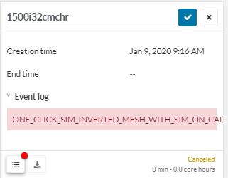
Could you start a sim run on anything right now and see if it gets cancelled immediately with that error?
yep cancelled immediately. I also got logged out randomly
EDIT: Meshing seems to be working though
Since you are getting into it ![]() this is worth reading:
this is worth reading:
And this guy (Aydin) has GREAT CFD videos…
https://www.youtube.com/channel/UCcqQi9LT0ETkRoUu8eYaEkg
thanks a lot!
I have updated the yPlusHistogram, to v204 code, here… Give it a try please so I know it works ![]()
I still have to download paraview but ill do that now and give it a shot!
Also what version of Paraview are you using? will the histogram work on earlier versions? i was thinking of using version 4.3.1