Optimizing mesh quality and Y+ layer formation on an FSAE car

I am talking about overall making your max refinment level at 1 (or even 2mm) if you can, with geometry changes.

Twofold benefit:

  1. Fewer cells
  2. Easier to increase 1 st layer size with your personal restrictions on Final layer ratio…

That gurney flap could be 1mm or even 2mm thick and maybe the same for TEs (but perhaps pointing TEs is better)

I just assumed that the LEs would be a problem going from L11 to L10 but if they are already L8 then what is your LE concerns if max level somewhere else on the Geo went from L11 to L10?

If i change the smallest geometry surface to 1mm, i would also change my whole bounding box levels to reflect this surface selection. So i would have my max refinement level at lets say 10. which is currently at 0.97mm. My current surface refinement that my BL is based off of is at 1.9mm. So moving to 10 this would give me more cells and smaller Y+ ability

Level 0 (calculated) 1m
Level 1 0.5m
Level 2 0.25m
Level 3 0.125m
Level 4 0.0625m
Level 5 0.03125m
Level 6 0.015625m
Level 7 0.0078125m
Level 8 0.00390625m
Level 9 *.001953125m
Level 10 0.0009765625m
Level 11 0.0004828125m
Level 12 0.000244140625m

No do not change BMB size or cells, stay at 1m L0 size… I do not see why you want to change?

What is the 1st layer thickness in BL right now?

my only reasoning is so i can get in between the cell levels. Level 9 is 1.9, Level 10 is 0.97 … If i want to have a level at exactly 1.52 for example, then i would have to recalculate the level 0 to get this.

I see no need for exact 1.52, why?

These are my exact settings.

Inflate boundary layer settings - layer calculation Y+ Value
Layers 3
1st 0.001726 Y+ = 80
2nd 0.0018123
3rd 0.001902
Overall thickness 0.005451 Y+ = 255
Expansion ratio 1.05
Min thickness 0.001m
Final layer thickness (RATIO)
Relative 0.97
Absolute 0.001902

1.52mm cell size is an example that the only way to get an cell size between a pre-set level 0, of 1m would be to re calculate the cell sizes back from a wanted cell value (in this case 1.52) which would change the level 0 size

Need link to sim run that the last y+ histogram was made from please…

I see no reason in your post that you need a level with a 1.52 mm size…

NO i dont need one… it was a hypothetical Scenario where if someone wanted to have a cell size that lands between the already determined cells, in my case 1.9 and 0.97. that it could be calculated back and a new level 0 created.

Here is the LINK

Good, then we don’t need to change level 0 of 1m (which I have explained why it is good earlier)…

Im still a bit stuck on our recommendation. The goal is to have a much thicker 1st layer. This means that I would want a 1st layer Y+ of 150 ( 0.003233 or 3.2mm) or higher to have it about doubled of my current Y+ of 80.

At 0.003233m or 3.2mm it would force me to use level 8 (0.00390625m or 3.9mm) in order to have my first cell (and with a low expansion ratio) final layer thickness to be at or below the level 8 cell size.

I currently have ALL surfaces at level 9 due to the region refinement not allowing my higher surface refinements for TEs and gurney flap to mesh

Here is a close up of my trailing edge element mesh

And here is the confirmed cell size using the distance marker at the bottom of the simscale viewing pane. The with of the trailing edge cells are level 9 but they are squished to fit on the face. I believe that the TE is about 0.48mm thick
image

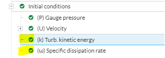
Ok so thinking though this again, let me know what you think:

The mesh and cells you are seeing in my previous posts and what is currently being simulated are at level 9 region refinement and therefore surface refinement.

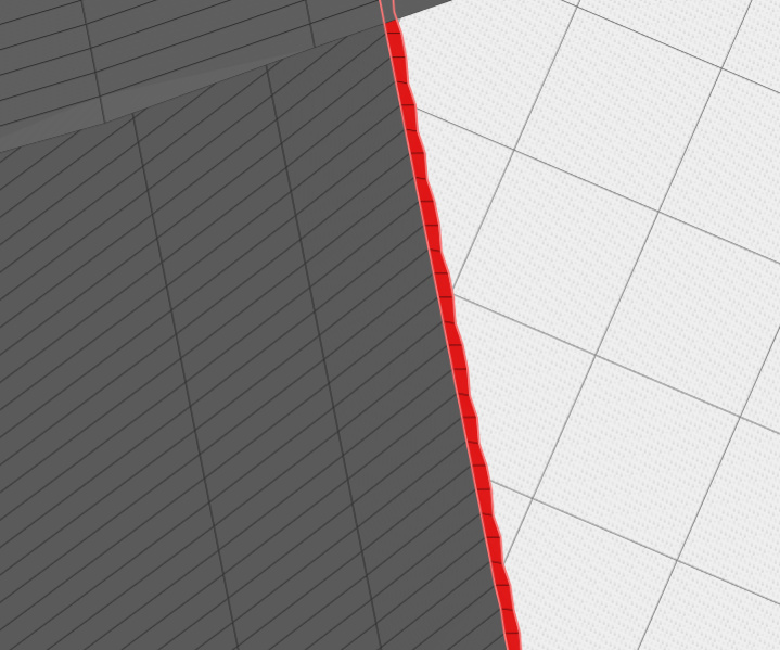
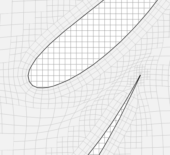
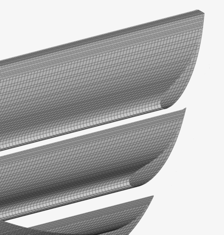
Level 9 mesh quality at leading edge
image

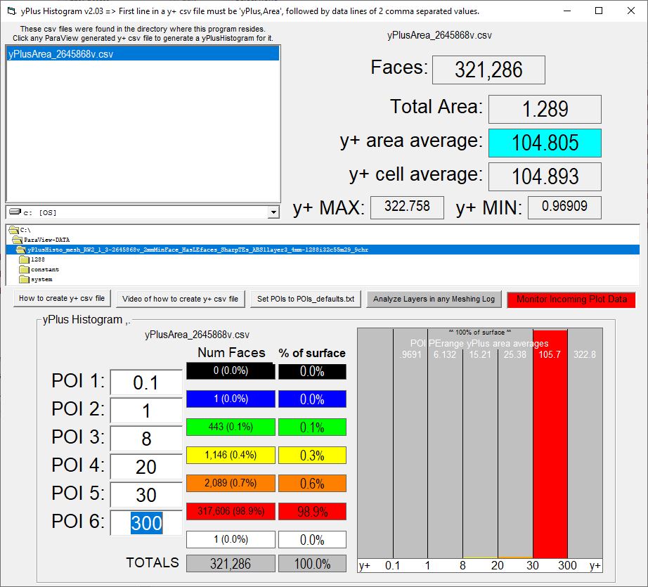
I need to have BIGGER cells, so that any boundary layers to be inflated at a higher starting Y+ will fit under this value. In this case my target is 150 which is a cell size of 0.003233m. The next level up (reducing the level) is level 8 with a cell size of 0.00390625m. This allows my Y+ requirement of 150 to be met.

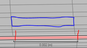
HOWEVER, a level 8 cell size is quite large and in previous meshes as shown below

Level 8 leading edge mesh quality

What i “think” i need to have for increased Y+ values and to be able to still retain mesh quality around the Leading edge could be to add a feature refinement. This has been the only tool that allows for steps in surface mesh size while keeping the same region refinement size. Without it i cannot have accurate meshing on the geometry and keep a large first layer for Y+. I need a level 8 or 7 region, and therefore surface refinement. With increasing levels for edges.
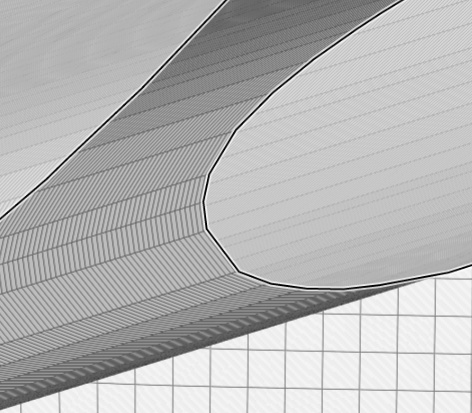
From RW test 2.0
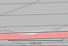
boundary layer still looks good up until trailing edge - feature refinement may be reducing cells to below min thickness of 0,001 setting, - i can change this to 0 and i also wont be using level 10 as shown in this trailing edge

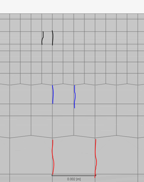
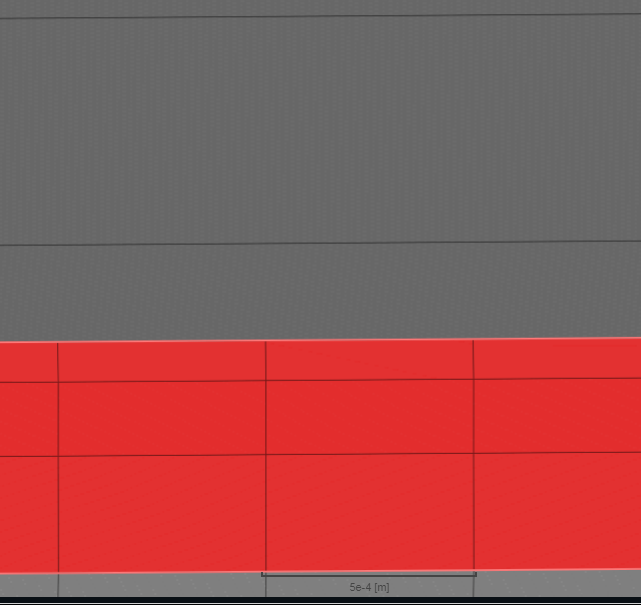
Going back through the only mesh i did with a feature refinement, i found something interesting. I had set the refinement to 0.0004 at level 11 and 0.0009 at level 10. The next picture is the trailing edge of the main wing, where it has a level 9 surface in red, level 10 in blue, and level 11 in black. The next picture is of the Main wing trailing edge face, where there are 3 cells, all refined to level 11. The main wing Trailing edge is most definetly bigger then the element trailing edge. I dont know the exact measurements.

Main wing Surface

Main wing Trailing edge face

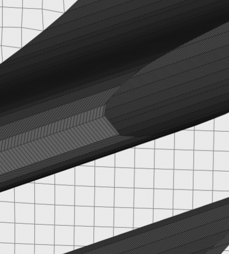
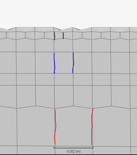
Now here is the first element trailing edge on the wing surface. Again level 9 in red as surface refinement level, blue is level 10, and black is level 11. HOWEVER in the following picture of the trailing edge face. It refines to only level 10??? Is it possible that the level 11 cells in the element Trailing edge are causing the jaggedness. It seems like the mesh is trying to go from level 10 on the wing surface, to level 11, then back again to 10 to match with the trailing edge face.

Going back to the main wing surface-to-trailing edge interaction. there are no jaggeded edges. I suspect this is because the trailing edge face, and the wing surface share the same refinement level. So the mesh isnt trying to snap back to a lower level between a high angle face.

1st Element wing surface at trailing edge

level 10 refinement on element TE face
image

Now im thinking to have a feature refinement of level 9 at distance 0 to edges, This should theoretically give me the same edges as a level 9 refinement but now i can use a level 8 region/surface refinement.

Attempting this now.

And sorry for all the questions / never ending trials of new theories that you probably know the results of before i do them haha

1 Like

So my trailing edge suspicion was confirmed. the feature refinement was able to get good meshing on the TE’s and there are no/the same jagged edges as my other meshes. Since my leading edges are still not that great, i am considering splitting the geometry. However maybe i should do a Y+ analysis of this run and see how it goes. Im not sure how important the mesh quality of the leading edge is. I know for real life performance, the leading edge is very important.

So, remember, Best Geometry is #1

So, with great effort (mainly because you use stl files to import your geo to SimScale), I made the CAD changes I have been suggesting:

  1. Make it so ALL faces on geometry are >=2mm
  2. Sharp TEs for this test
  3. Leading Edge faces so we can refine/layer them separately for some scenarios

I have made a project and imported my new CAD file into it (in STEP format, much preferred)…

Then, I decided to make a test mesh with a single layer on everything at 3.4mm thickness… Its is 99.5% layered:


.
.
.
I now have a sim run running that you could try your ORSI plotting on (WAIT TILL 800 or more iterations are done before you try ORSI so you don’t get confused right away) :wink:

A couple things, I changed quite a bit of your sim setup, ask me about any of it you don’t understand or feel uncomfortable with…

  1. You really should leave the write interval of ‘Forces’ and ‘Coefficients’ results at 1 iteration… ORSI works better with that…
  2. No need to start BMB at y0.001m
  3. I used a Custom Inlet so we can set k and omega there
  4. I have had so many issues with symmetry planes I don’t use them anymore… A slip walls works just the same (I have verified that many times over)

We can discuss the 1 layer theory later, I have not much time left today.

I just stopped it when both CD and CL were 1% stable over 500 iterations with a 50 iteration moving average :slight_smile:

I like it when a plan works…

I doubled your 1st Layer thickness and now we only have 0.4% of surface area with yPlus < 20 :slight_smile: :rainbow::sunglasses::rainbow::sunny::beers:

1 Like

Ok going in order

  1. I agree geometry is very important. The connection between correct geometry and mesh quality/no problems is very strong

I agree sharp TEs are better then 1-2mm TEs, I will change this on all wings

Edit sorry i keep forgetting that i cannot assign a region assignment to faces, this is really a feature i would like to have. Forget all that is written below

Here is where i have a problem. I see you split the face, but did not assign a higher level. Keeping the leading edge faces at level 9 (because the region refinement wont allow for switching these to level 10) seems like a waste of work. There is no change. The only reason i wanted to split the leading edge face is so that i could apply a level 10 region refinement and surface refinement to this area. This would increase surface mesh quality, especially for the smaller radius of the element leading edges.

This is great work! im fine with having one layer and that it is bigger the the region/surface refinement if it means almost all Y+ values are between 30 and 300!

Do i have to download your ORSI program as well? can you send me a link?

Will do sir!

I was only doing this because the FSAE tutorial said to

I was looking at changing K and omega here. i didnt know you could do this right in the velocity inlet… what is the difference?

image

I will start using slip walls instead of symmetry

When you mean stop the sim i assume you mean here? Just hit cancel when i reach the 1% and under stability of Cd and Cl
image

P.S. I have copied your split LE project and made a new trial HERE I have tried to change just the elements to level 10 along with the region refinement. This should help with element leading edge quality as the element have the smallest LE radius.

I had to leave something for you to do :wink:

Yes, when I monitor manually a sim run with ORSI plots, I set the ‘Write interval’ and ‘End time’ to LARGE values (usually 5000), in this test I used 1500 since I wasn’t sure I would be around at the end…

I am not sure what the difference is but I prefer to use the custom inlet, it is more flexible.

ORSI plot monitoring is in my yPlusHistogram v204, just put a copy of the exe in your browser downloads directory where it will scan that directory every second (when Monitoring is ON) for new CSV plot files that you download from SimScale. Turn monitoring ON, on the form that appears when you click the RED button… I haven’t put those (or any) instructions on the feature in the program or ReadMe file yet, that is on my ToDo list :wink:

Lately I have been struggling with issues similar to you when I try to layer the treads on my CyberTruck tires to a y+>20…

You have the same issue between your wings…

Using 1 layer solves the yPlus issue but leaves doubt if the turbulent BL is fully analyzed in thickness. We have small hex cells close to first layer and the solvers have good resolution there if we have not captured all the turbulent thickness.

Fortunately I believe that the k-w SST turbulence model does still evaluate wall function in Hex cells, so I am hoping we are OK.

My CyberTruck mesh looks good but I have not been able to converge a run with 1 layer on the tire treads. It is timely that your 1 layer meshes’ sim run converges well.

I think you should make a CAD file without the middle wing, make a mesh for a ‘standard’ 3 layer with 1.3ER at 3.4mm 1st layer AND a mesh with a single 3.4mm layer… Then run a fully converged sim run on each… Then we can evaluate the results difference… I suspect there will be very little difference…

Are you up for that :question: