The bug: copied below, is preventing me from running simulations on a large aerobody mesh. Any ideas?
[[18906,1],8]: A high-performance Open MPI point-to-point messaging module
was unable to find any relevant network interfaces:
Module: OpenFabrics (openib)
Host:
Another transport will be used instead, although this may result in
lower performance.
[:00149] 15 more processes have sent help message help-mpi-btl-base.txt / btl:no-nics
[:00149] Set MCA parameter “orte_base_help_aggregate” to 0 to see all help / error messages
mpirun noticed that process rank 9 with PID 159 on node exited on signal 9 (Killed).
Hi @uwmidsun!
Make sure you post the project link so that we can have a look at it.
Best,
Jousef
Hi @uwmidsun,
Which particular simulation run are you referring to? There are various simulations that you’ve run.
Cheers.
Regards,
Barry
Any of the simulations under Simulation 2
Hi @uwmidsun,
I will be looking at run 3. The cause of the simulation crashing is due to your assignment of the boundary conditions. You have assigned the entire domain from top, the sides and back to a pressure outlet which is incorrect and may cause the simulation to hit continuity errors as you have encountered. From the logs the simulation instantly crashes which means that a major error is present which is probably the BCs.
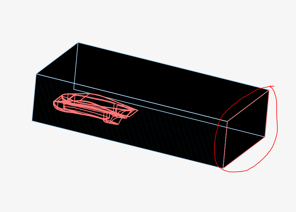
Only the circled face in the figure below should be a pressure outlet. The top, and sides of the bounding box (with the geometry as reference) should be a slip wall. In addition, you also need to assign the geometry as a no-slip wall. The assignments for inlet and floor are correct.
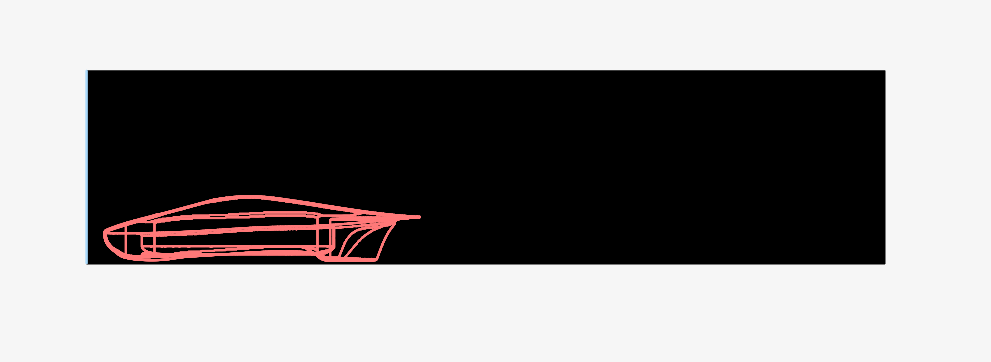
I assume you assigned the top and side walls as a pressure outlet to represent free air of sorts. With my recommendation to instead assign the top and side as slip walls, I’m sure you would be wondering if the wall effects may affect the simulation results. Yes they will, however, we can negate these effects significantly (affects the final result by less than 0.01%) by increasing the size of the bounding box vertically and laterally. I recommend increasing the height of the BBox to 3 times the height of your geometry and 3-5 times the width of your geometry as well. This brings me also to the figure shown below where the front of the geometry is too close to the inlet and may adversely affect your results as the flow does not yet have time to develop. Similar to the recommendations for the vertical and lateral distance increase, you should increase the front distance of the BBox by at least 2-3 times the length of the geometry.
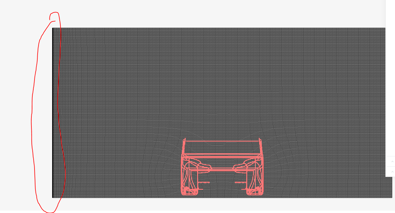
Lastly, while your mesh is error free and generates the layers well, (referring to the figure below) I assume that your floor is supposed to be at bottom rather than the side. As such your floor layer generation is incorrect as you can see in the circled area and will need to be changed.
Hope this helps.
Cheers.
Regards,
Barry
1 Like