Hello
i m working on project of aircraft. I m supposed to predict first points of separation.
Aircraft is set up so that root of wing has 4° higher angle of attack than the rest. Fuselage is also done in such way that it creates diffusor and should cause huge separation before anypart of wing stalls.
Trouble is, the last point to separate is the root. There must be problem with setup of simulation, code or numerical settings but this result is non-sence.
Could you please have a look ? Lift readings are really good compared to wing tunnel. Only the separation point is really bad.
What can be done ?
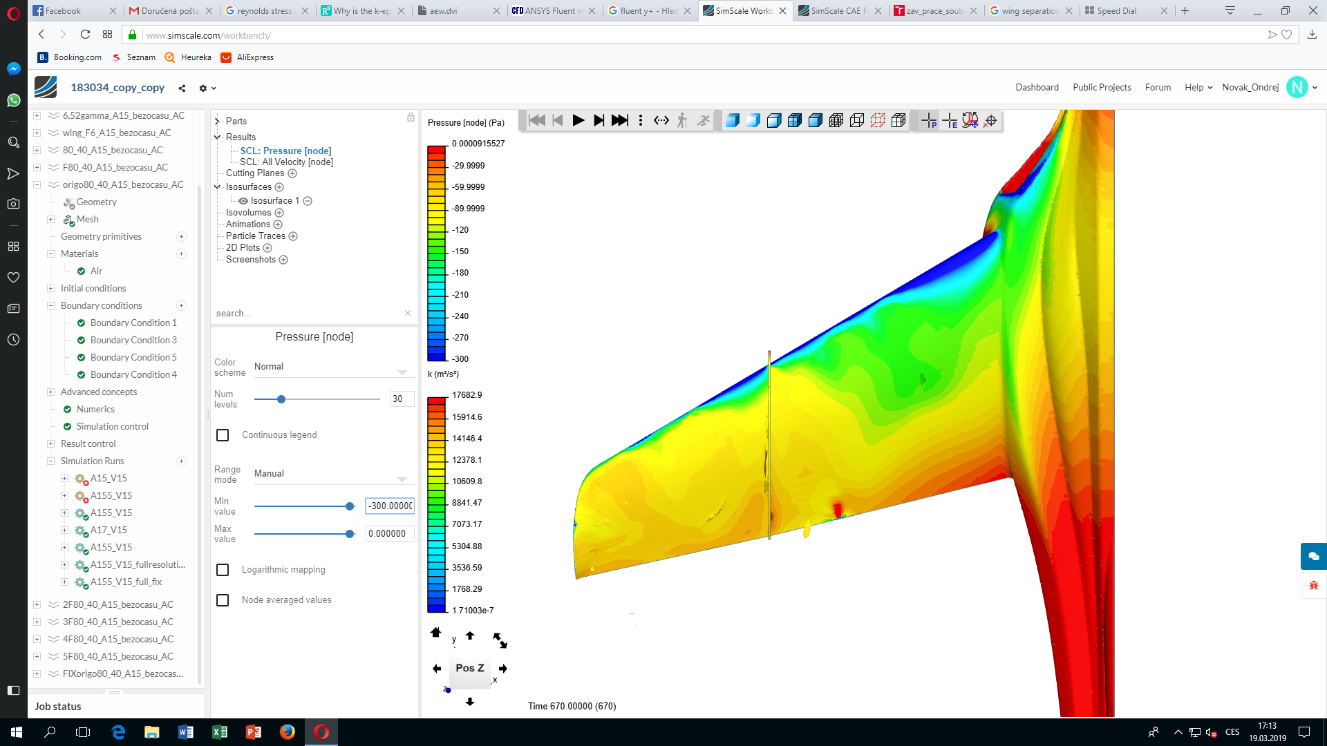
project is 183034_copy_copy by Novak_Ondrej | SimScale … the last run and last simulation setup should be the best. But it is not.
Thank you
Hi @Novak_Ondrej!
Very nice project, I love it! Can you please let me know what criterion you are using to say that the flow is separated? Have you already plotted skin friction drag over the chord length and see where c_f is equal to zero? Afaik deriving the separation point directly from a “pressure diagram”, namely c_p value prediction is not 100% accurate when it comes to this type of issue.
How good are your lift values compared to your measurements?
Best,
Jousef
I generally plot velocity surfaces having vector of velocity against main stream.
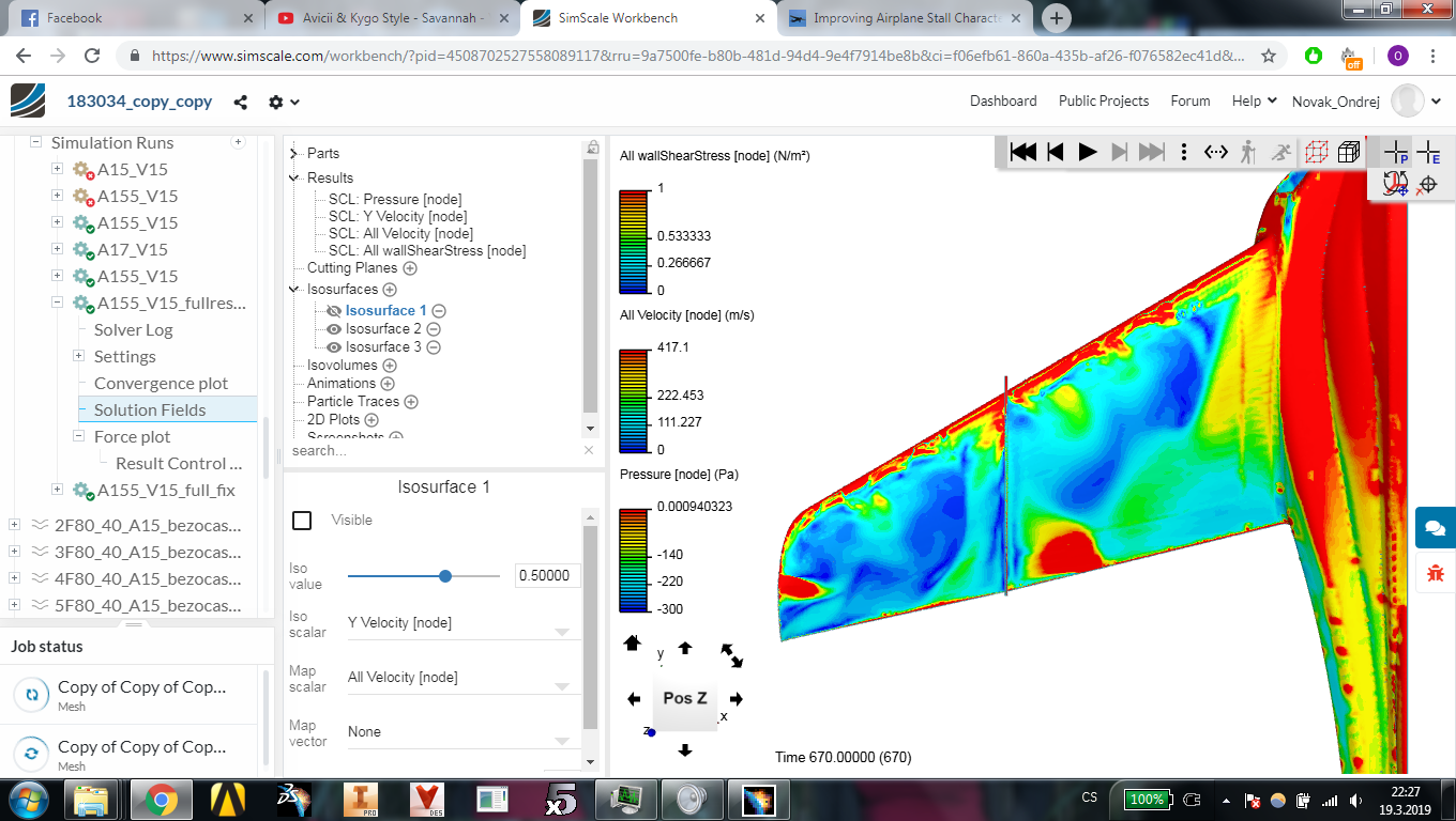
If i plot wallshear stress ( used to calculate skin friction drag), then where wallshearstress is =0 than that regions can be considered separated ?
Well here is plot of wallshearstress … if where =0 means separation than the whole wing is separated except wing root … but wing root has highest angle of attack by far  That root will stall soon but as last … i dont understand why
Hi @Novak_Ondrej,
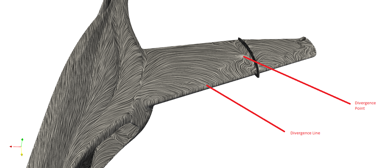
When looking at separation, it is indeed zero shear stress your looking for, however, its best to actually put surface lines on and look for the divergence to make it more clear. You can use paraview for this called surface LIC.
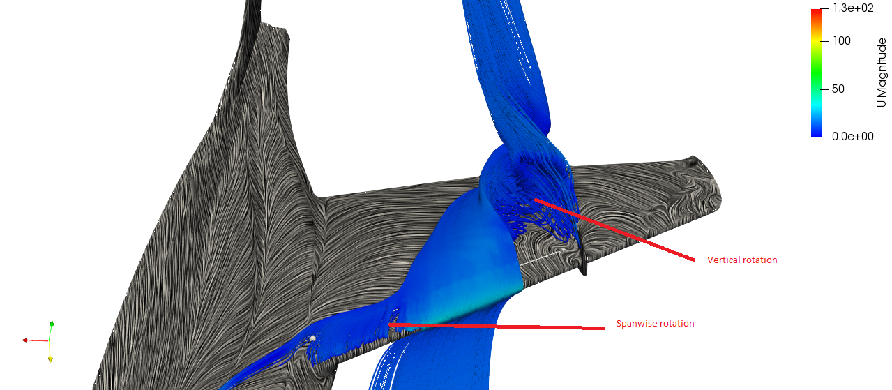
In the image, you can see the divergence line at the LE of your wing, that signifies a leading edge stall, and looks like it pretty much covers the entire wing. the divergence point actually shows the point where a vortex forms above the surface vertically. This can also be visualised by putting streamlines seeded just behind the divergence line:
Hope this helps,
Darren
5 Likes
Did not know about the trick with the LIC filter Darren but makes complete sense using that - nice one! 
Cheers,
Jousef
1 Like
yeah this is great idea thanks for that
But there is probably another issue.
I found this paper from NASA https://hiliftpw.larc.nasa.gov/Workshop1/ParticipantTalks/SS2012/6-Moitra-hilift.pdf
They are stating that “Tetrahedral grids constructed from tertrahedral-prism grids by
subdividing the prisms do not capture SOB flow separation due to
excessive dissipation of HSV vortex systems” - this could be my issue 
But “Tetrathedral-prism hybrid grids have made qualitatively correct
predictions of SOB separation”
Whats the difference between these two meshes ? Can i create the correct one using simscale ? Can this be done in ICEM meshing ( i have acces to it ) ?
Thanks a lot !
1 Like