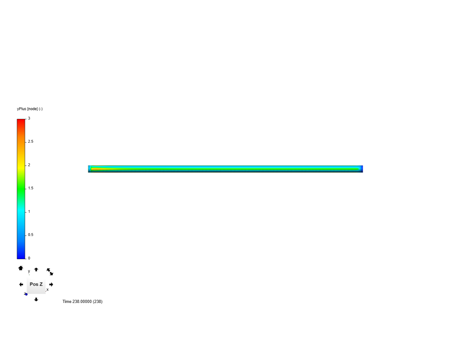
I have some results from a CFD analysis that look odd to me. It is a very simple analysis of a 2 m long pipe 51 mm in diameter and 0.5 m/sec flow rate through the pipe. The simulation converges just fine but when I plot y+, the values are different on either side of the pipe. Why would y+ vary around the pipe?
The two plots are shown below and here is the project link:
I would suppose that this is coming from the mesh quality, namely coarse mesh near the wall and non-normal velocity distributions along the pipe and of course high y+ at the inlet - have you tried refining the mesh and had a look the result afterwards? Will have to check it myself first what’s going on there. @Get_Barried & @DaleKramer, you guys have discussed quite frequently about these issues as far as I can remember, any ideas from your side?
Yes, I am using a medium mesh with wall inflation so the mesh is fairly well refined. Also, the mesh is identical on both sides so the the y+ values should be identical as well.
The issue with SnappyHexMesh (the meshing algo) is that it is an iterative mesher and generates layers upon layers. If you read through the workflow of Snappy, you will see that there is a step where it attempts to conform and reiterate the mesh to best fit the geometry.
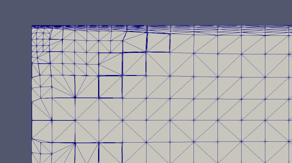
This is good when complex geometries are involved as it means less work individually refining specific areas which would take a lot of time. But in your case of a simple geometry, it continues to do the same thing. Referring to the figure below, you can see that the ends of the pipe are more refined than say the middle. The layers are iterated accordingly and thus you get a deviation of y+ as you progress through the geometry.
The potential fix would be set a topological entity set for the inlet and outlet so that the automatic mesher will not attempt to refine the ends of the pipe. By controlling this you force the mesh to be consistent through out the pipe and as such the layering process will also be consistent through the iterations. However, this specific workflow may not work as the automatic mesher has changed since the last time I used it. If we are unable to control the mesher, then we will need to switch to the parametric one where we have greater control.
Try this out and let us know how it goes.
Do consider your simulation as well. Selection of turbulence model and usage of wall functions will dictate your y+ values.
I was not referring to the inlet and outlet of the pipe. Please look at the pictures again. If I rotate the pipe 180 degrees along the x axis (Pos Z vs Neg Z), I get a completely different y+ value on the opposite side around the circumference. 180 degrees opposite one side of the pipe (around circumference) mid-pipe, should have identical results because the mesh is identical.
I am aware of your issue in that you want the y+ (layering) to be consistent throughout the pipe lengthwise.
What I mentioned previously is a possible solution to control the mesh so that you can achieve that. In order to control this we need to take special care of the inlet and outlet of the pipe as non-intuitive as it sounds. This possible fix also applies to ensuring that both ends of the pipe can have the same y+.
The mesh is not exactly identical as the iterative nature of SnappyHexMesh means that this is not that simple to control.
Do correct me again if you feel that I completely missed the mark.
Hey guys,
As Barry correctly mentioned the mesh is not symmetric (see picture posted by Barry above). You can see the difference in the first layer thickness across the pipe influencing the turbulence variables and consequently the y+. Once the issue with the mesh is fixed you should have no such problems with “strong” asymmetric y+ distribution again.
I guess I had assumed the mesh would be symmetrical since the pipe is symmetrical around the x-axis. I am more interested in the maximum y+ on the wall so I will just reduce the layering size to make sure all the wall cells are less than 1 y+ for resolving the wall.