Nonorthogonality in enclosure

Perhaps I am using a rather unorthodox approach of uploading photogrammetry meshes for CFD analysis, which are processed in Meshlab and Meshmixer. The other perhaps unorthodox aspect is that since I am trying to obtain drag coefficients of cutting armatures (arrowheads essentially) I am including a tube that extends to the back of the computational domain as a stand-in for the trailing shaft. This is attached in Meshmixer. The false shaft and armature are left as separate bodies so Cd can be isolated on the armature. This is in a viscous Newtonian incompressible at 25-40m/s.

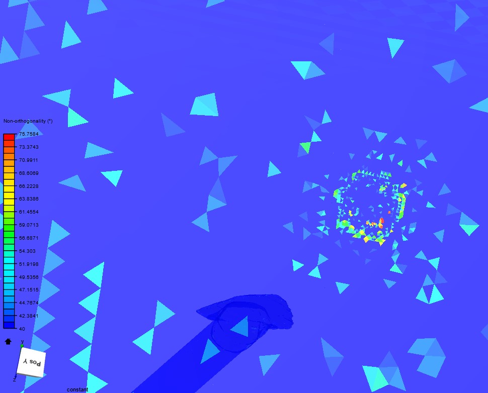
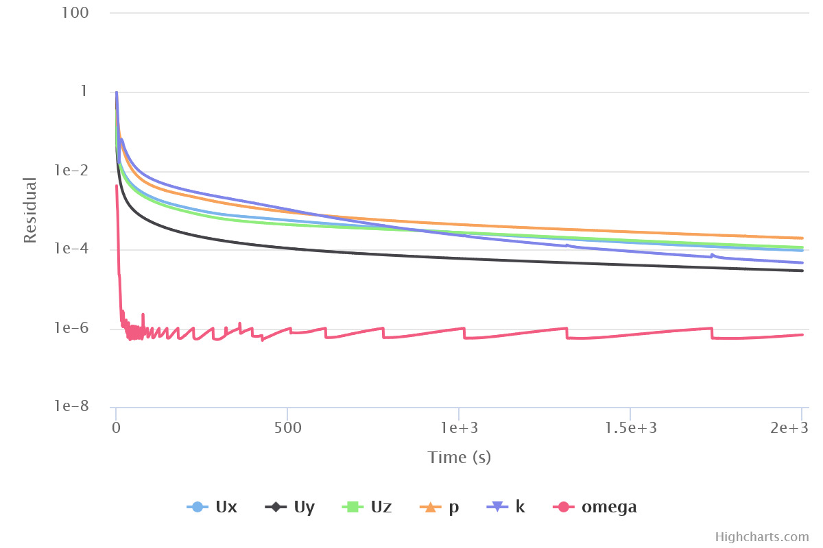
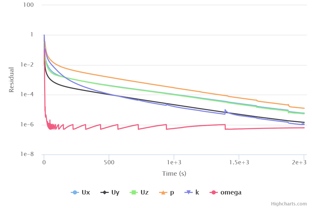
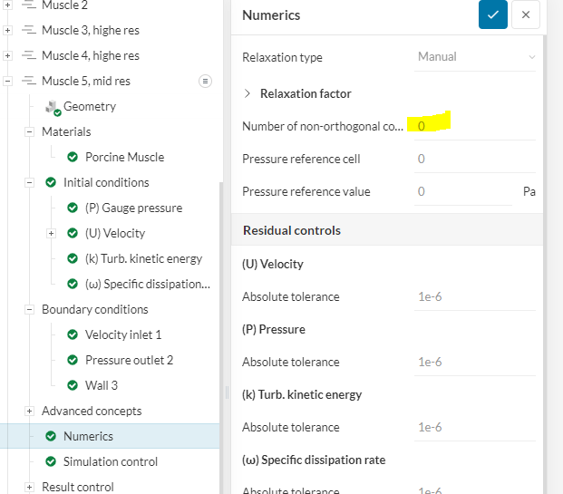
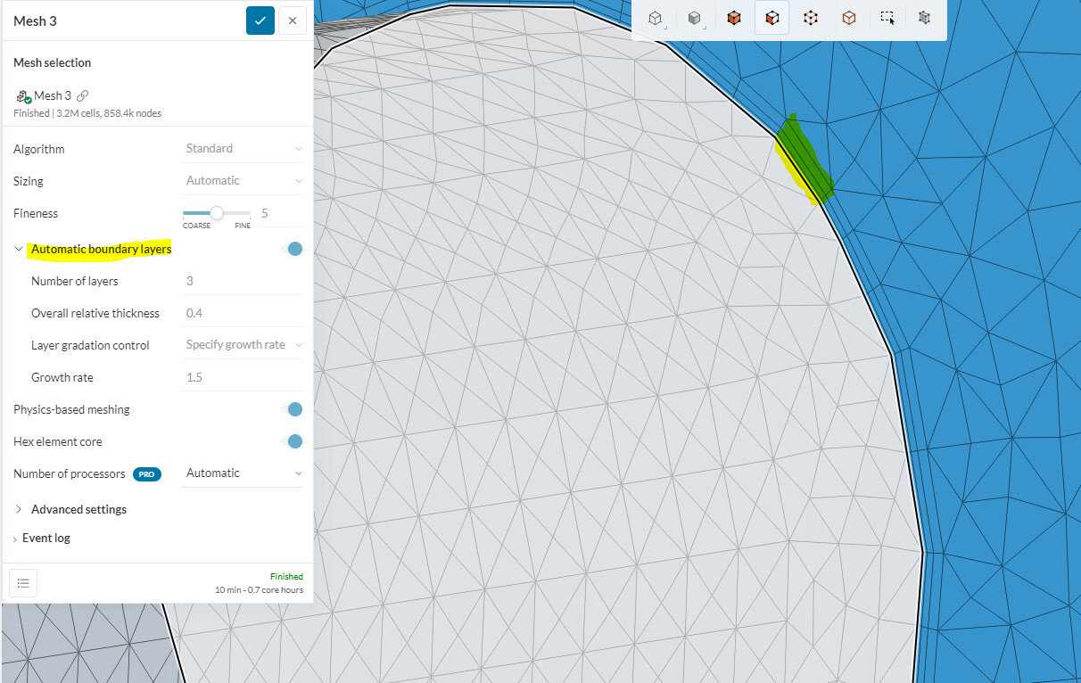
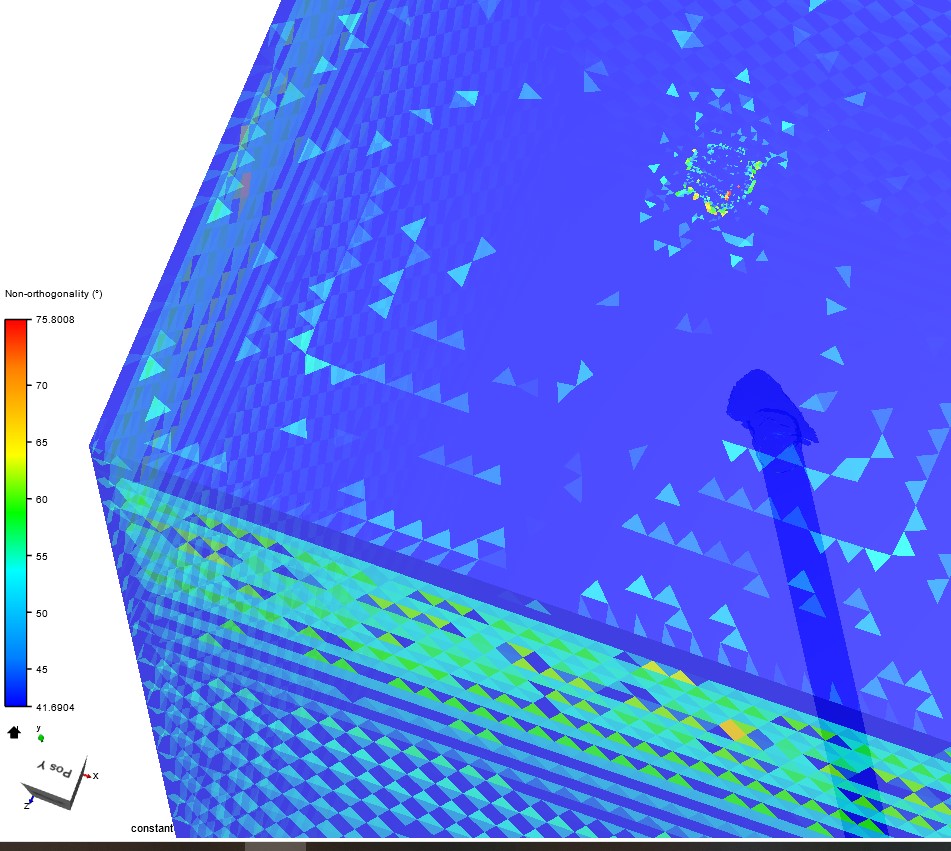
Finally after solidifying in meshmixer with >.2mm thickness SimScale does not complain too much about the models. But since I would like to achieve convergence in my lifetime and without hogging more computer power than necessary I apparently have to try and fix nonorthogonality >70 in the generated meshes using the SimScale standard mesher, and hope this is almost the final step to have stabilized Cd measures. It is hard to find documentation on how to do this that doesn’t involve going back to cleaning in the CAD software. There appear to be only a few mildly troublesome spots on the models I could potentially resolve, but through the quality checker I am seeing that actually the most troublesome areas are in the enclosure! I cannot find anything on how this should be resolved. Ideas?

Muscle 5 mid res provides a good example (https://www.simscale.com/workbench/?pid=6836371537479817522&rru=0121a3c6-66ea-4e9e-b727-a806e42f1cac&sh=33&ci=59cd26a6-0bb0-455e-acbd-2bcb7efbcfa1&ct=MESH&mt=SIMULATION_RESULT)

tetAspectRatio max=8
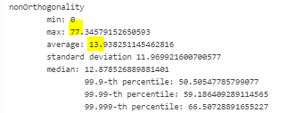
Non-orthogonality max=77
tetEdgeRatio max=7
volumeRatio max=10

I fixed troublesome areas on the model and ran new meshes. As far as I can see the highest non-orthogonality is definitely on the enclosure, mainly at the inlets and outlets.

Hi there, this is Fillia :smiley:

I would like to know the method you are using to prepare your CAD model, if that is alright with you. Correct me if I am wrong:

You are modelling the arrow as a surface and export it as stl. Then you use a separate software and add a thickness of some mm. You also include a shaft, and then use the CAD mode to create the Enclosure. Is that right?

Best regards,
Fillia

Hi Fillia,

That sounds mostly right. I am using Agisoft Metashape to generate meshes from photographs. Then I align and scale them in Meshlab. I make the models solid (where I add thickness as well) and also add the false shaft as a second solid body in Meshmixer. Here I can also perform spot repairs on problematic areas. Finally I use Meshlab to “repair nonmanifold edges by splitting vertices.” This dramatically reduces the size of the stl files.

I have tried various other cleaning and repairing filters in Meshlab as well, but so far the workflow I just described does the best job of creating models SimScale will accept.

I have not seen much work yet using photogrammetry for CFD analysis, except a recent paper from last year, “Identification of aircraft aerodynamic derivatives based on photogrammetry and computational fluid dynamics”. Their analysis was performed using Ansys.

Thanks,
Devin

1 Like

I should clarify a few more points.

  • I have tried meshing in Simscale with both the standard and Hex dominant algorithms. When I use the latter the worst non-orthogonality occurs on the armature models, not on the enclosure.
  • I have run the mesh using coarser and finer (up to 9) settings in SimScale, but non-orthogonality still occurs on the enclosure, according to the quality checker.
  • I have switched off Physics-based meshing, thinking this could help the problem of non-orthogonality at the inlets and outlets (namely the inlet is where it is worst). But this did not resolve the situation. As can be seen from the first attached screenshot, there are also troublesome spots on the side (slip) walls of the enclosure. Max non-orthogonality remains in the 75-84 range. It is generally lowest with the default settings and physics-based modeling on.
  • I have tried increasing the length of the front of the enclosure.

Non-orthogonality implies to me that the models should not have sharp angles, which is a necessary feature of models of sharp armatures. So perhaps non-orthogonality is something I will have to live with, and the simulations will require many iterations? Perhaps increasing relax factors could help, I have only tried the default settings in both Automatic and Manual relaxation types. The higher settings in the Manual mode did seem to help, and the simulation may converge after ~3k iterations. But this seems an inefficient workflow for the rest of the models if non-orthogonality can be resolved.

Default automatic relax factors:

Default manual relax factors:

The nature of the models does not clarify why the quality checker sees non-orthogonality on the enclosures. The highest values occur at the inlets where the mesh appears to be quite fine, perhaps owing to the nature of a physics-based mesh where the modeled body has a sleek and sharp profile (Cd should be very low)? But why does it also occur on the side walls?

1 Like

Hey @depe1522

I have a few points that may help.

The degree of Non-Orthogonality of a cell is measured as the angle created between the vector normal to two cells shared face and a vector between their cell centroids.

So yes, non-orthongonallty could be created by sharp geometry edges, and to a degree, you must live with this.

It is also important to remember that with the standard mesher, being based of a tetrahedral cell, you will have inherent Non-orthogonality in the mesh. This is most likely why your hex-dominant mesh didnt show non-orthogonal cells on the enclosure walls. Here is a link to why this is:

https://www.pointwise.com/theconnector/2014-November/How-Do-You-Define-Good-Grid.html?utm_campaign=Brand%20Awareness&utm_source=Y%20%20Page&utm_medium=Conn-DefineGrid-Nov2014

Here are a few helpful links on non-orthogonality. The first is useful as a general guide but the videos from Aidan are pure gold. His fluid mechanics 101 channel is extremely useful in all areas of simulation

PPT on different quality definitions / mesh creation in general
Video on Non-orthogonality

This being said, i think your non-orthogonality levels are well within a reasonable level.
image

One thing you can add however, if you are interested in reducing the impact of error-inducing, non-orthogonal cells, is adding a few non-orthogonal corrector loops (1-3).

HOWEVER, i have notice that you are uisng the automatic boundary layer addition for your standard mesh. While this is acceptable for quick simulations, if you want really realistic Cd results, you will need to find out the exact Y+ value you need and then apply the correct boundary layer cells. This will have a MUCH HIGHER impact on false Cd levels then a few non-orthogonal cells.

ALSO you must decide if you are trying to measure in the viscous sub-layer (y+ less the 8 – less then 1 is better) or in the log- law region ( y+ between 30 and 300) . For your case i would recommend measuring the viscous sub-layer (y+ less the 1) because your main goal is measuring Cd.

Finally, there are some great articles, tutorials, and documentation within simscale. This is where i have found a lot of information:

Good luck!

Dan

2 Likes

Hi Dan,

Thank you for the excellent information. I am busy researching appropriate y+ values and look forward to achieving more accurate Cd measures. This was a great help.

Devin

1 Like