New and need advice - testing a 3D-printed GPS mount

Hello. Non-engineer and first-time SimScale user here. I’ve created a 3D-printed GPS mount that holds a Bluetooth GPS module. My mount attaches to a RAM mount (very common commercially available suction mount, if you’re not familiar), which I will attach to the windshield of my car.

For the sake of learning, I’m trying to use SimScale to see if my mount will survive an accident. I’ve modeled it and run two simulations on it (one using aluminum, to test it, and one using the material specs provided by the 3D printer). The project is available here:

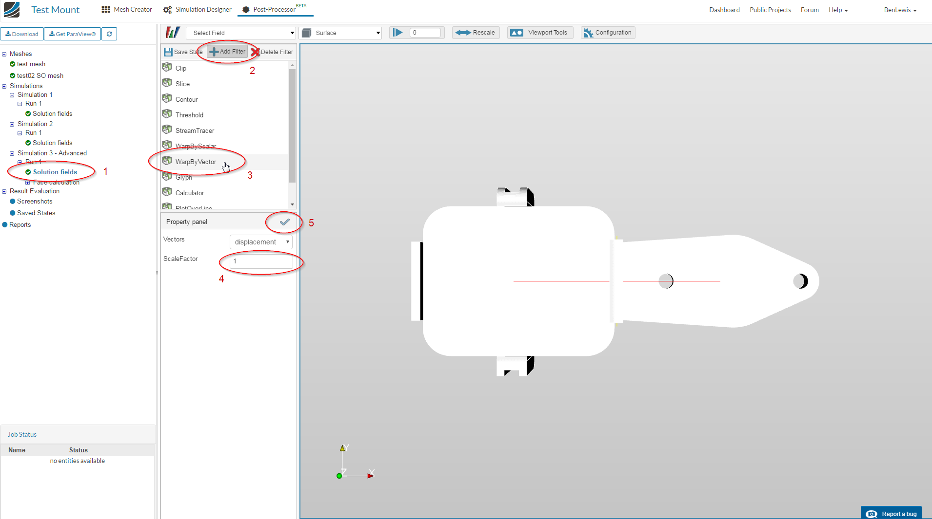
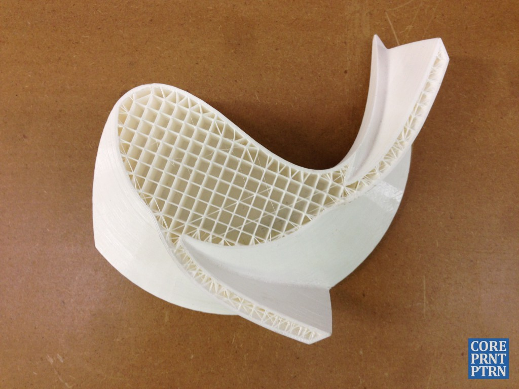
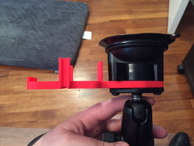
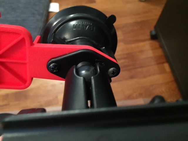
I’m looking for advice on how to configure the simulation for most realistic results. Here’s what the mount looks like in real life:

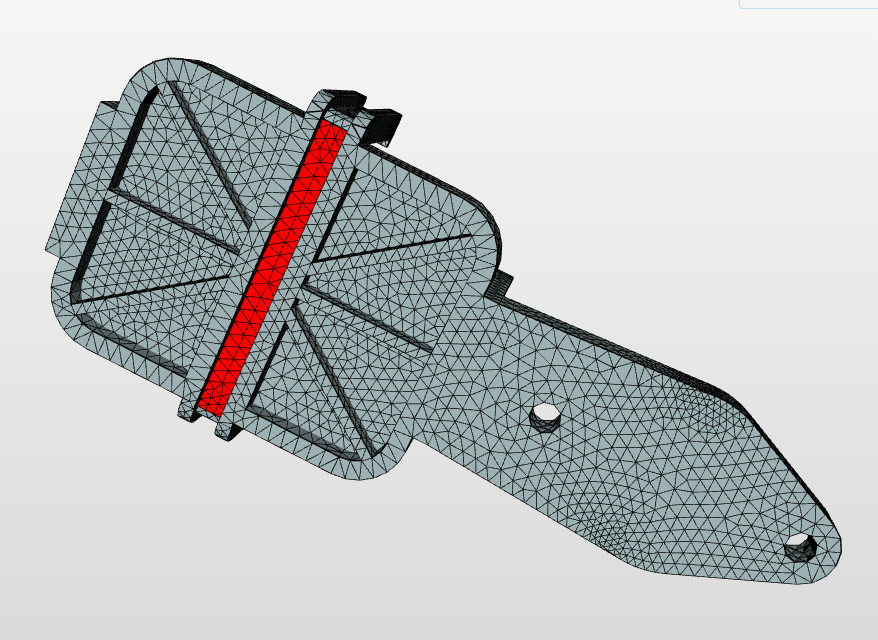
Here’s a screenshot of what I selected as my constraint. My logic here is that this is generally the section of the model that is sandwiched in the RAM mount, so it is constrained. I know I need to tweak the model to reflect the actual area sandwiched, but for purposes of learning, let’s go with this for now. Is my logic sound? Should anything else be selected/not selected?

Here’s a screenshot of what I selected as my load. My logic here is that the 110g GPS module is bearing on this surface. For my load, I did the following math:

110g GPS module * 200G simulated accident load = 22kg load
69mm surface length X 54mm surface width = 0.003726 m2
22kg load / 0.003726 m2 = 5904 kg/m2 = ~58,000 Pa

Are my math and logic generally correct? I understand that there are tons of factors, such as the vectors of the accident forces, the angle of the windshield, the fact that an accident is dynamic and this is a static test, etc., but for learning purposes, am I on the right track?

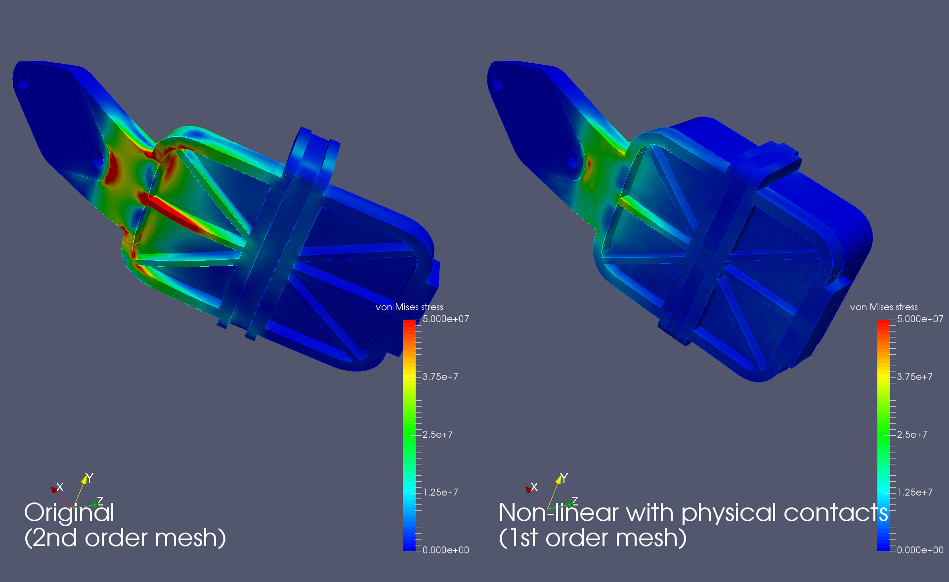
Any advice for making this test more realistic?

Also, last question…

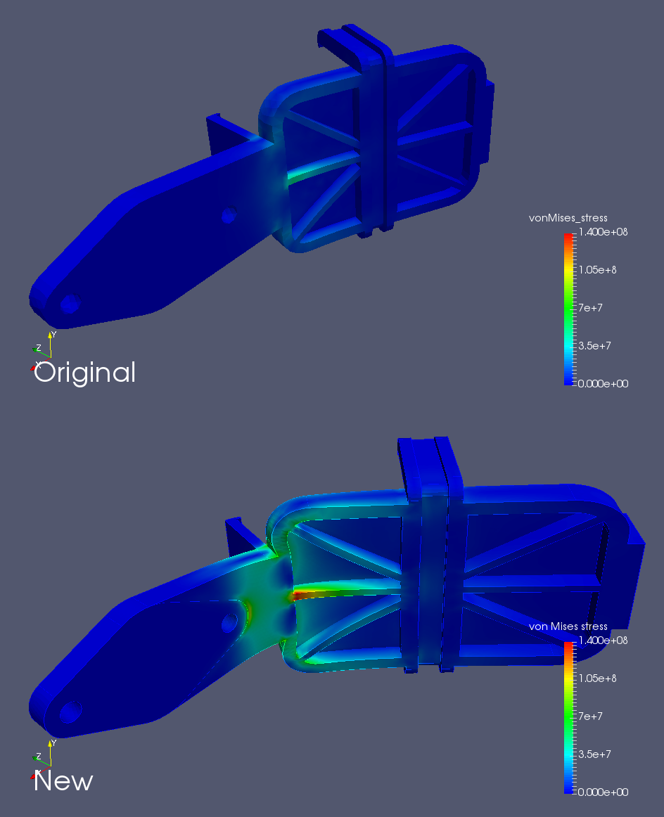
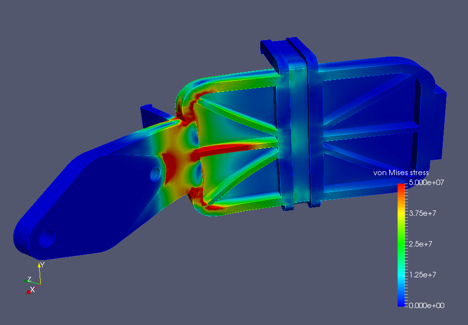
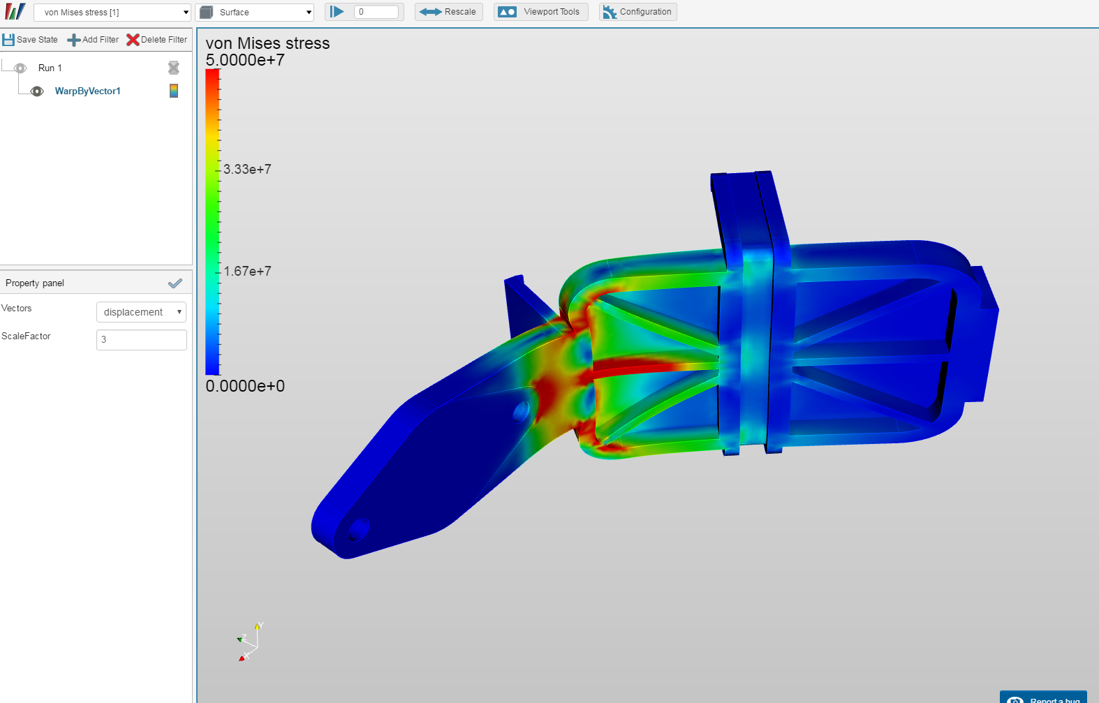
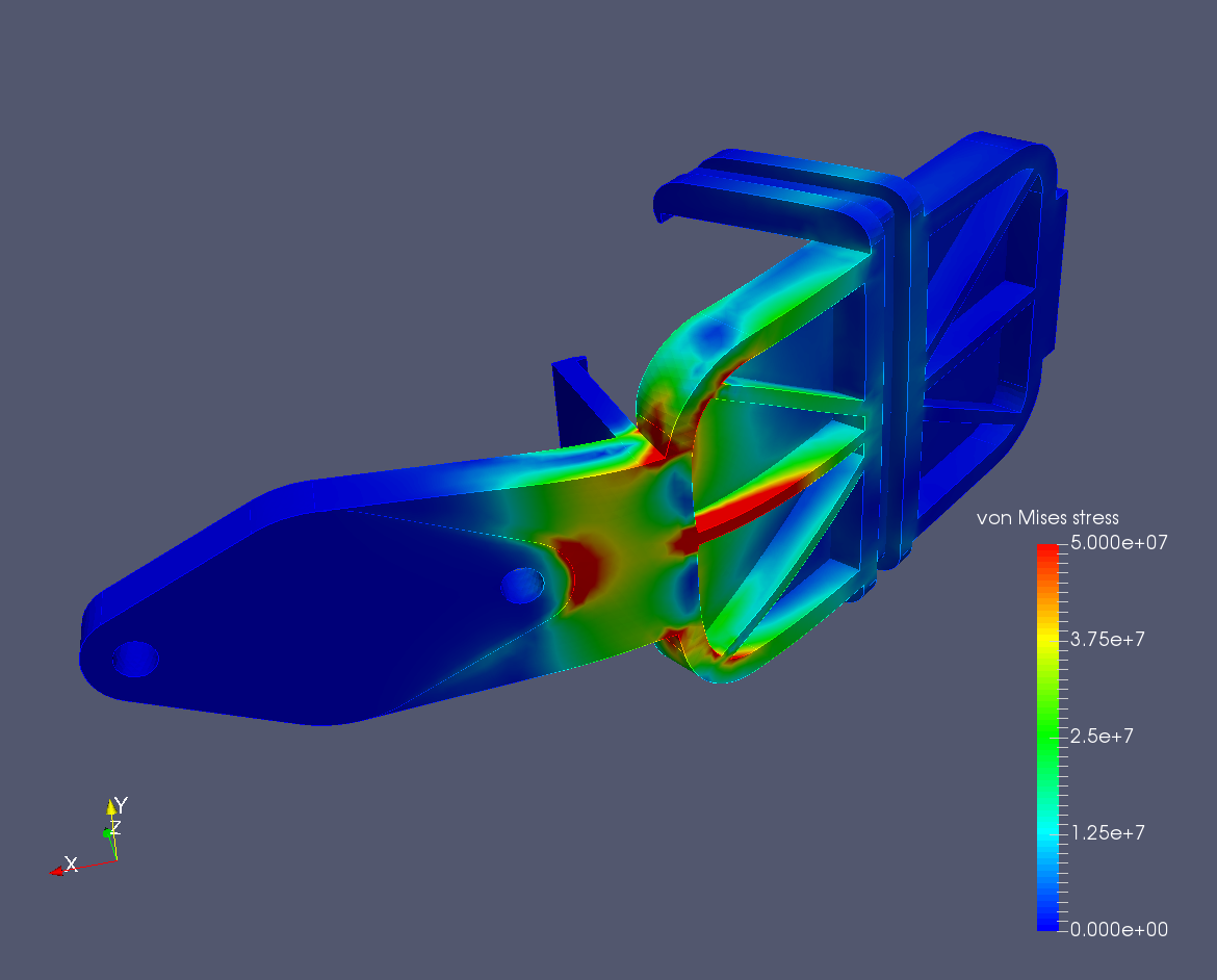
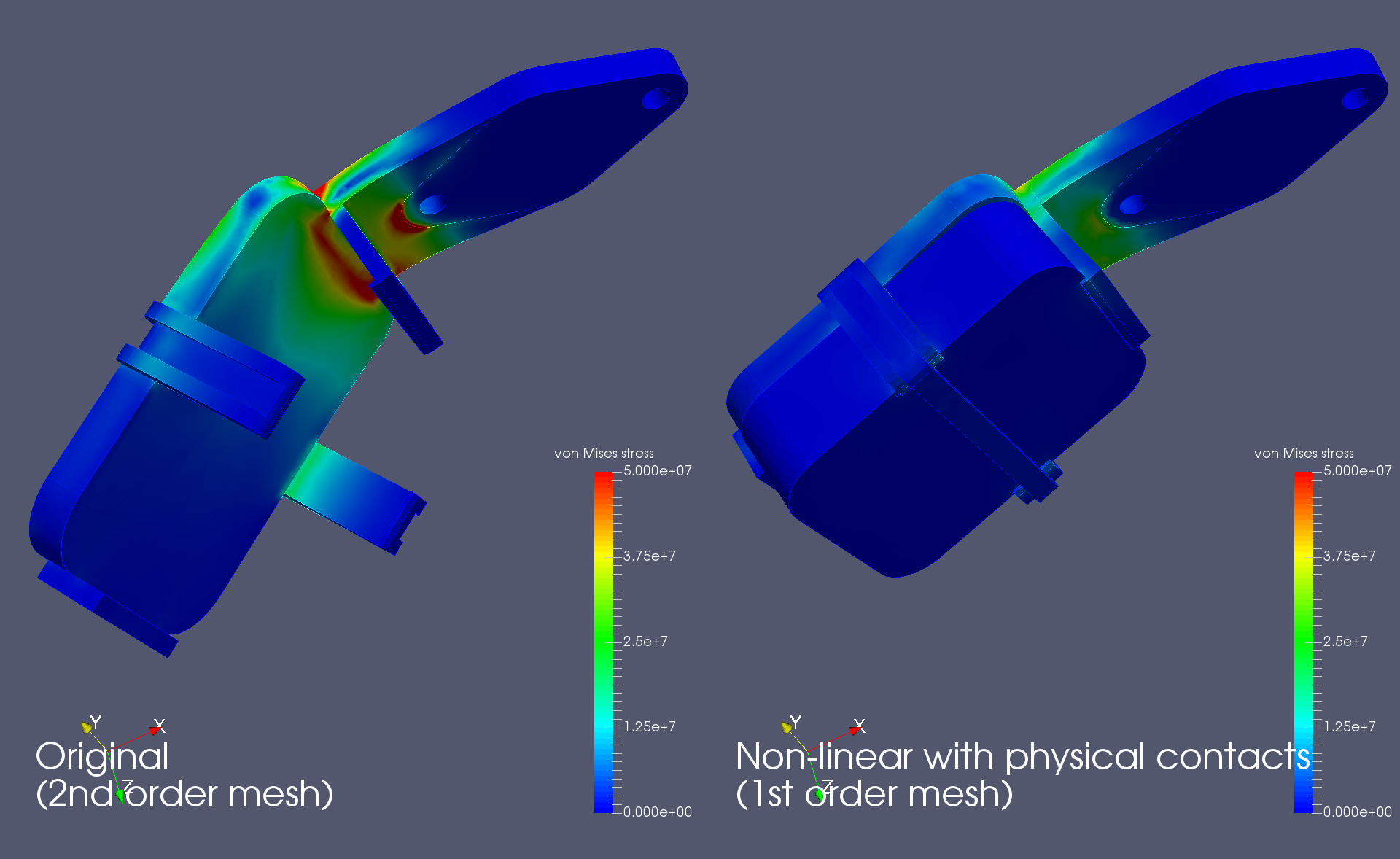
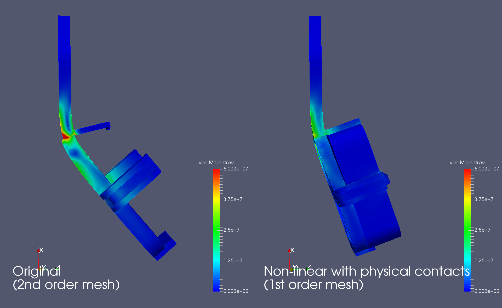
In the Post-Processor, when vonMises_stress is selected as the field and the scale is set to automatic, is it safe to assume that where the part is red is where the stress has exceeded the critical value and thus the part will start to yield?

Thanks in advance for the help! Apologies if I sound like an idiot - just trying to learn.

2 Likes

Hi mculik5,

This should get you a bit closer.

Link to public project

Link to import project

Here is my logic:

  • The highest stress will typically occur close the mounting bracket. Therefore it is not valid to constrain the entire mounting face. I have split the mounting face to provide a more accurate fixation.

  • A second order mesh will generally give you more accurate results. See this post for more details.

  • Switching to the Static Analysis - Advanced type gives you more options for loading, including force. This eliminates the need to do a pressure calculation.

  • The loading has two components

    1. force due to acceleration of the attached GPS unit (applied as a force)
    2. force due to acceleration of its own mass (applied as a gravitational load)
  • Result control measures where added to check reaction forces (Fz = 281 N) and maximum displacement (Dz=24 mm).

The color of the stress plot has nothing to do with yield stress (unless you intentionally set it up that way). For example, if the yield stress of the material is 50 MPa, setting the scale upper limit to this value will show everything that has exceeded yield in red. Below is an example.

I’m not sure where you got your value for the collision acceleration from (200 G). To me it seems too high. Even if the GPS bracket where to survive such a collision I expect the impact zone would have entered the cabin and the bracket (and vehicle) would be a write off anyway.

As a rough guide, if a vehicle is doing 60 km/hr and stops over a distance of 1 m (crumple zone). The average acceleration would be:

$$a = \frac{v^2}{2s}$$
$$a = \frac{(60/3.6)^2}{2
1}$$
$$a =139 m/s^2$$
$$a = 14 G$$

Does this help? If you have any more questions please let me know.

Regards, Ben

5 Likes

Ben:

This is extraordinarily helpful! Thank you!

Regarding the 200G number, it was an arbitrary selection on my part, meant to be extreme. I did some very brief reading and found that the G-forces in racing car accidents can approach 200G for VERY short periods of time. I won’t be using this in a racing car, but figured I’d give it a test at the very extreme end of the G-force spectrum. Completely agree that something in the neighborhood of 50G is probably more than sufficient for safety.

A few questions about your work:

  1. How did you split the mounting face? I wanted to apply the constraint exactly as you did, but couldn’t figure out how to get that face to be independently selectable, either in Onshape or SimScale.

  2. I haven’t played with the SimScale interface too much, so might be a simple question, but how did you get SimScale to show the deformation?

Again, thank you!

Hi @mculik5,

You cannot split faces in SimScale, this needs to be done to the geometry before importing. To split a face in Ohshape you can follow the instructions in the link below (see section at the bottom titled “Splitting a face with sketch entities”.

There is also a video in the link below (see section called “SPLIT IMPROVEMENTS”)

I used ParaView to create the deformed plots but you can also use the on-line post processor in SimScale. The technique is pretty much the same for both tools. Here are the steps using SimScale’s post processor.

  • In the post processor navigate to the simulation of interest and Select solution fields. This will load the simulation results.
  • Select “+ Add Filter”
  • Select “WarpBy Vector”
  • Set the ScaleFactor to 3 and select the tick to apply
  • Disable the “eye” for Run 1 and enable the “eye” for WarpByVector1. This makes only the deformed plot visible.
  • With WarpByVector1 selected choose a solution field from the drop down menu. In this case I chose von Mises stress.
  • The result should look like this.
1 Like

Nice work @mculik5 and @BenLewis!

What would also be relevant to know (perhaps even more than the crash resistance of such a device) is if the mount would stay attached when you drive on bumpy roads (harmonic analysis) or over a pothole or curb (transient dynamics).

Best,
Richard

Hi @rszoeke,

I agree. Actually I was thinking that I would not use a collision scenario at all to determine the strength required for this device. The strength required is probably better defined by the force required to separate the suction cup from the glass. The user should be able to take hold of the bracket and pull it off the glass without breaking anything. If the bracket can handle this then I would say it is fit for purpose.

Of course the device should also not fall off the wind screen over bumps and pot holes. If this is an issue then further analysis (as suggested) could be done. I guess the sort of things that could be concluded from such an analysis are maximum arm length, maximum weight and minimum suction cup size.

@mculik5, I wanted to say well done on your first attempt at this simulation! Given that you are relatively inexperienced (not an engineer and first time SimScale user) I thought you did remarkably well.

@BenLewis and @rszoeke:

Thanks for your replies and the compliments. Though I’m not a professional engineer, I’m a pretty good Googler, and was part of a Formula SAE team in college. Both of those things helped me out a lot in this case. And thanks again, Ben, for the extremely helpful info about splitting faces and WarpByVector.

I’m definitely going to play around with other scenarios. The ideas you guys suggested are pretty neat. That said, the RAM mount suction cup is surprisingly solid, and I’ve never had it come off the windshield. The suction cup diameter is about 2.5". At 14.7 PSI atmospheric pressure, that should give about 70 pounds of holding power. Given that the whole setup, with my iPhone installed, weights about 1.5 pounds, I figure it’s good for nearly 50G.

The purpose of my GPS mount is to use with data logging software on my iPhone at track days (driving my car at speed on a racetrack, but not trying to beat anyone…just for fun…). Rules generally state that anything inside the car needs to be secured so it can’t become a projectile in the event of accident. I recognize that, in the event of a serious accident, the RAM mount is probably going to come off the windshield, so the stuff I’m simulating here really won’t come into play. That said, it’s good to know I can, in theory, trust my mount. It seemed a bit “flexy” when I first received it, but apparently it’s plenty strong.

Thanks again!

Hi @mculik5, now that I understand your application your collision simulation makes perfect sense. It sounds like you’re simulation is on the right track.

To validate your simulation results you should be able to apply a known force and measure the resulting deflection. In your case applying a force of 28 kg in the center of the bracket should result in a deflection of 24 mm at the far end of the bracket. Of course you would not want to damage your bracket so you can scale the applied force down. Applying a force of 7 kg in the center of the bracket should result in a deflection of 6 mm at the far end of the bracket. Keep in mind that your 3D printed part may not be internally solid. Typically it is only the outer surfaces of a 3D printed part that are solid. If this is the case this will reduce the stiffness of your part. Here is an example.

This may explain why your part feels more flexible than you were expecting.

1 Like

Thanks again, Ben. Definitely planning to set up a physical experiment and see how close it is to my SimScale results. Fortunately, my part was printed on a fancy 3D-printer by Shapeways, and is solid all the way through.

New question:

I’m trying to refine the simulation to be more accurate, but I’ve forgotten vector math and trig from high school. When installed in my car, the mount will be parallel to the windshield, which is obviously at an angle to the ground. In the event of a frontal impact, the crash force would come at an angle to the mount. To refine the simulation to be more accurate, I’m trying to figure out how to “split” the force vector to apply it to the Y/Z-axis faces of the mount. Here’s a VERY rough image showing what I mean.

The angle between the hood/ground and windshield is 125.4 degrees. It’s also important to note that the mount faces forward. From the driver’s seat, you see the X-shaped ribs on the bottom, not the GPS unit. Finally, the mount is designed so that a zip-tie can be placed around it, securing the GPS unit inside of it.

My logic is that in the event of an accident, the GPS unit will move up/positive on the Y- and Z-axes. It will exert a force on the zip-tie, which will exert a force on the mount. Here are the faces I’ve selected for the force to be exerted on:

Y-axis:

Z-axis:

Questions:

  1. Does this make sense? Do you agree with my face selection? Is this the right way to do this?

  2. Any ideas on how to do the vector math to figure out what values to use for each load boundary condition? I think it’s F/cos(35.4) and F/cos(54.6), but that seems to result in force vectors that are larger than the original…

Thanks again!

Hi @mculik5,

To resolve the forces into the Y and Z directions you can use the following equations:

$$F_y = F\cos\theta$$
$$F_z = F\sin\theta$$

where theta = 180° - 125.4° = 54.6°

I have updated my public project to show how I would apply the loads. Here are the results.

This approach is okay but it can be done better. You will get better results if you model the GPS unit and zip tie. You can then use physical contacts to ensure the various bodies do not penetrate each other.

If you are interested I can show you how to set this up.

3 Likes

@BenLewis - Again, thank you! Turns out my initial Googling and interpretation were correct, and I actually ran a simulation with those Fy/Fz forces last night. Too bad I overthought it earlier today…

Would love to learn more from you about including the GPS unit and zip tie in the model, but I also want to be respectful of your time. If it’s really no issue to you, though, I’d love to learn more.

Let me know what you need me to do. I presume model the GPS and zip tie?

Hi @mculik5,

I’ve set up a non-linear analysis with physical contacts. See my original public project for details (simulation Simulation 8 - FO NL).

https://www.simscale.com/projects/BenLewis/test_mount

So far I’ve got a first order simulation working. Here are some screenshots of the results.

You should be able to use this simulation as a guide for your own geometry (if it is different from what I have modeled).

The latest simulation has significantly less stress than the original simulation. This is partly because the GPS unit adds support to the bracket and partly because I’ve used a first order mesh. I’m working on a solution with a second order mesh but it’s not there yet.

When I get some more time I’ll explain what I’ve done to set up this simulation. In the mean time if you have any specific question please let me know.

@rszoeke, the Extract Block filter in ParaView does not work with these simulation results. I would like to use it to display individual bodies from this simulation. Why does this not work?

Hi @rszoeke, I’ve having trouble getting a second order version of this simulation to solve. When you get the time could you please take a look at my project and give me some tips?

Regards, Ben

Thanks, @BenLewis!

I took a look at your setup and noticed the contacts. I’ll have to poke around a bit, but at least I’m pointed in the right direction.

The fact that the GPS unit itself reinforces the mount is what I expected would happen. Definitely seems like the mount is plenty strong as designed. I may play around with optimizing it to save material.

Again, appreciate all the help and education.

Matt

Hi @BenLewis, thanks for reporting this. The problem is not specific to this model. By upgrading to a recent Salome version the behavior of the MED reader of Salome has changed and now all blocks are automatically merged at reading.
Thus after exporting to VTK only one block is available. We are currently looking into a work-around of this regression.
Best,
Richard