I am planning to run a simulation to investigate the problem of natural convection over a heat sink and I have some doubts regarding which analysis type I should choose in order to do so. I have been reading that CHT would be a possible choice but I am not sure. Thus, I have two questions:
1- Is it really possible to simulate a natural convection problem using CHT?
2- If so, which would be the boundary conditions? Just assigning no-slip wall boundary conditions to fluid and solid surfaces (except interfaces) would be enough?
Nice question, so do you have some project link to share with us to understand your project? It would be really nice.
Yeah, it is perfectly possible.
It depends because in our model you can have some conditions (e.g interface condition as you mentioned) that we must to have in account to set the boundary conditions. Thus, in this case a project link will be very helpful. If you have multiple solids, for example, each one will have a contact surface with other solids which will enable automatic detection of the interface and also defines a heat source for the external solid. But it is just one example for some possibility.
Nice to talk with another brazilian person here! Waiting for some feedback from you!
First of all, thank you very much for the fast reply. And yes, this is the link:
I have already set up a forced convection simulation, as you can see, and have obtained very good results (comparing with the experimental data I have). The natural convection simulation is the second one. I would be very glad if you could take a look at it.
As I was expecting, the natural convection simulation apparently did not converge (see figure below). I think one of the possible reasons may be the fact that when I changed the velocity inlet for a no-slip wall boundary condition, with the temperature option set as “set gradient to zero”, I did not, at any time, define which was the temperature of the fluid surrounding the heat sink. So, should I set a fixed value for the temperature in this no-slip wall boundary condition? And for which fluid faces? All of them?
Hi @gcleite96, so although the inlet-outlet will not be driving the flow, they still need to be defined to tell the simulation where air can naturally come in and out, otherwise, as you have experienced, air will circulate within the domain, continuously increasing in temperature. I would define a pressure inlet and pressure outlet, without applying a pressure difference, this will result in a natural flow due to buoyancy from the inlet to the outlet.
Thank you very much for the explanation and advice, @1318980! I will set up the simulation right now, applying pressure inlet and outlet boundary conditions, as you recommended. Hopefully, we will achieve good results.
Hi @1318980! Unfortunately, I have bad news. Apparently, the results for temperature did not converge again. I may be doing something wrong, but I really can’t see it.
I created a copy of the project in order to do this new simulation.
As can be seen in the second simulation (the one called “Natural Convection”), I have assigned the pressure inlet and outlet boundary conditions to two of the fluid faces. Even so, the temperature plot presents a slightly convergence behaviour, but not sufficient:
Hi @gcleite96, yes both using subdomain temperature is recommended regardless of having a good guess, this is so that the simulation starts with a temp difference between the solids. A longer run time might be required, first though, its best to check to make sure the setup is solid. At the moment I query the gravity direction, I imagined the gravity being aligned vertically, so the flow naturally passes from top to bottom, however, in this case, it seems to be aligned perpendicular to the ideal natural flow (-y opposed to z) is this what you intend?
So, the gravity direction should, indeed, be pointing to -y. But, when I was setting the pressure inlet and outlet boundary conditions, I thought they had to be assigned to the lateral faces, which were the ones that had been set as the velocity inlet and pressure outlet in the forced convection simulation. Seeing the results now, and the temperature distribution, I think what you meant to say before was that I needed to assign these pressure boundary conditions to the top and bottom faces, right?
Ok, I am struggling a bit, so the flow is flowing from Y- to Y+ boundary faces? if so I would suggest altering the shape of the domain, to be in the vertical orientation, what we want is to follow the rule of thumb that a bounding box (presuming it isn’t defined by some experimental setup) should be around 5 times the geometry size in each direction and even further downs stream. We don’t want results to be skewed by the bounding box.
Let me know if I have the wrong end of the stick though!
Best,
Darren
Well, when I set the forced convection simulation, the air was indeed flowing from +Z to -Z boundary faces. But, when I “shut down” this flow and let only natural convection takes place, the fluid, due to buoyancy effects, starts to flow from -Y to +Y, if I am thinking right.
So, I was going to ask you exactly what you’ve just said: it is better to invert the dimensions of the fluid region, right?
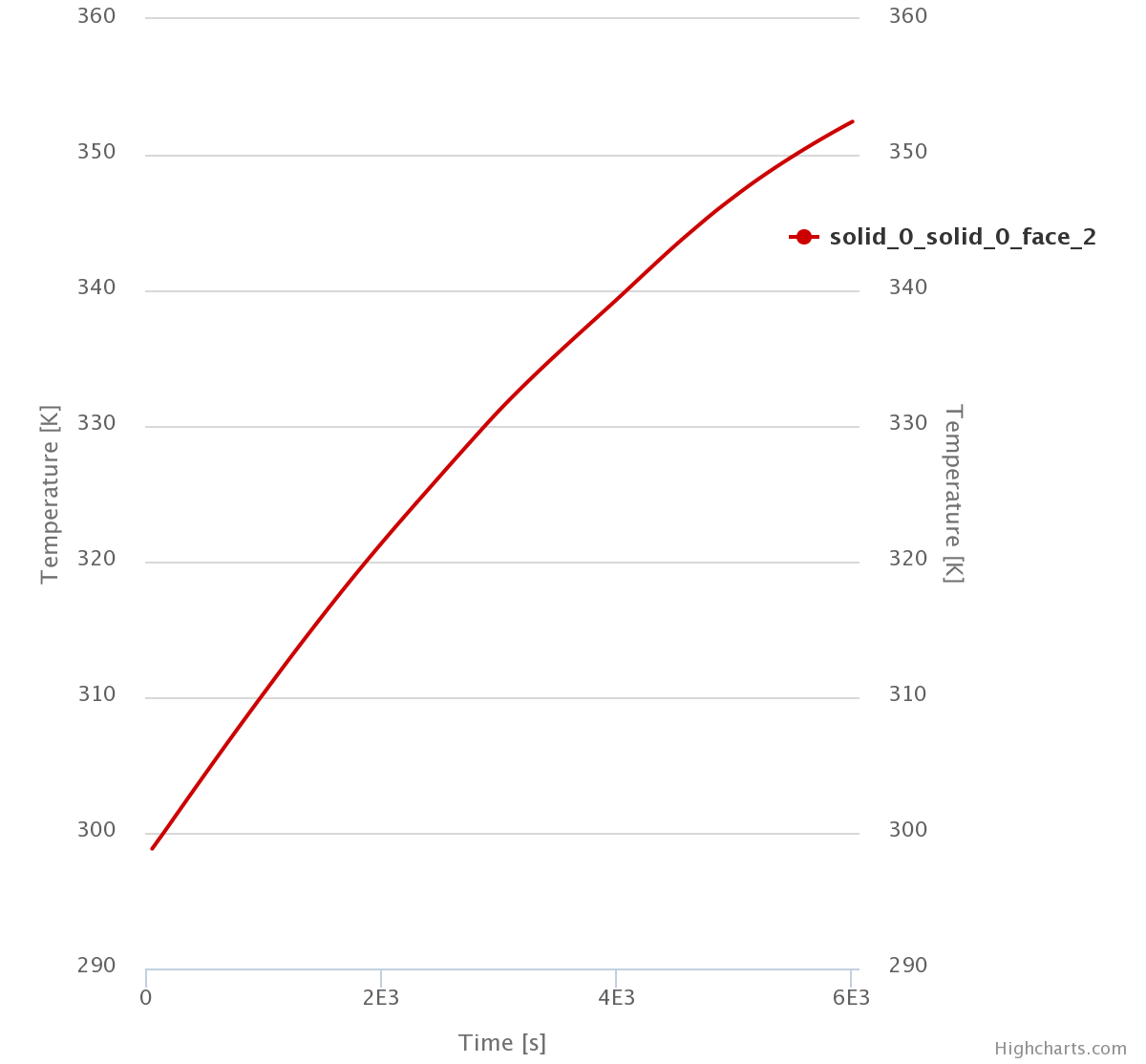
Hi @1318980! I finally achieved results close to the ones I was expecting. I think I just have to make some improvements now and everything will be good.
This was the first part of the simulation. The last one, and even more challenging, is to do the same but with a heat sink immersed in oil rather than air. I will open another topic on the forum to discuss how I could do it, if you could take a look at it I would be very grateful.
I have experimental data for both situations. After completing the simulations, I will write a small article comparing the results. I will share it here for sure.
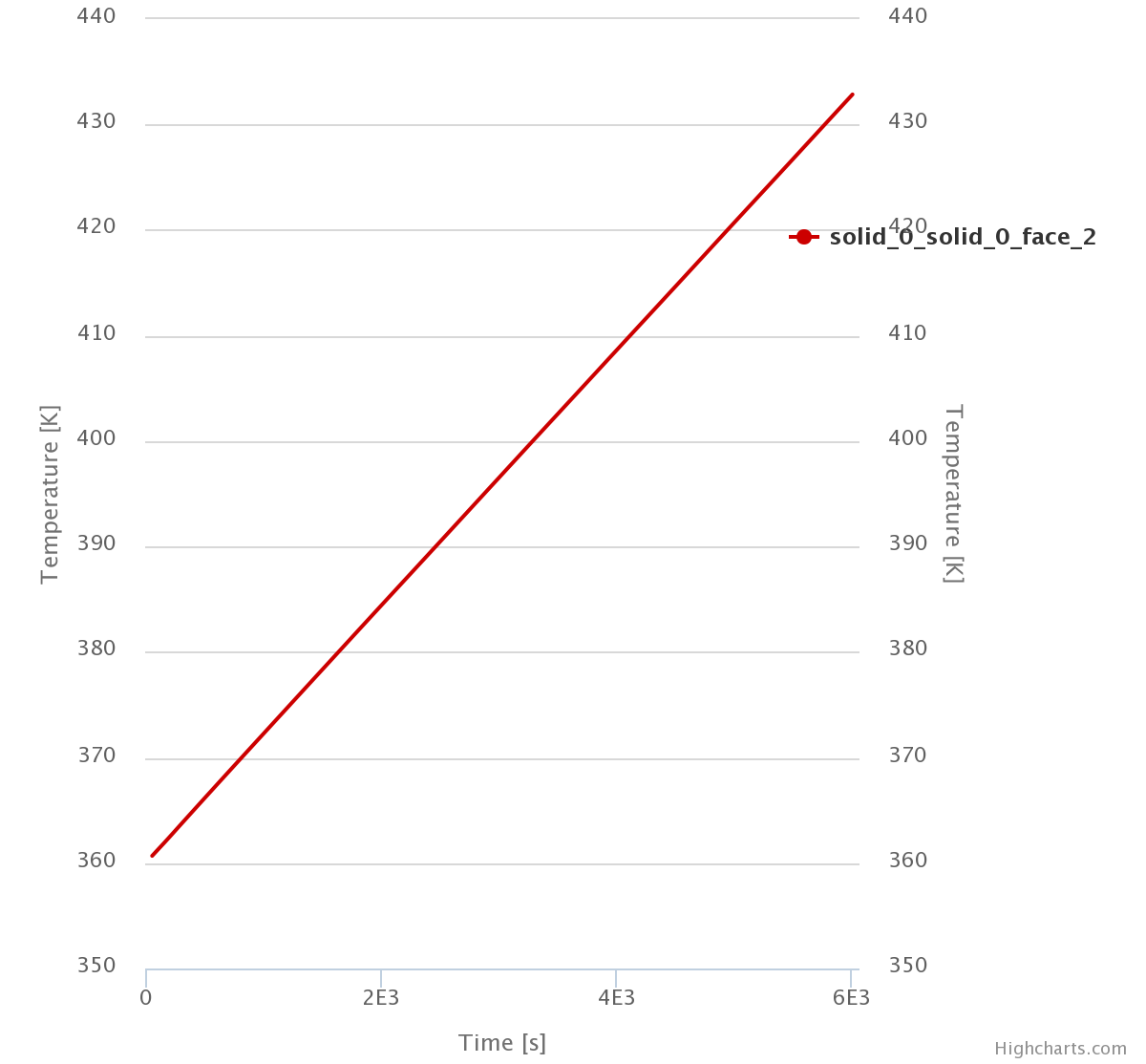
I have recently performed a CHT simulation of the natural convection observed in a heated heat sink immersed in air. The results I have achieved were good. Now, I am interested in doing the same but with a heat sink immersed in an oil medium. In order to do a small test, I have already set up a simulation and have run it for some hours. Apparently, the results would not converge, as the temperature measured on one of the heat sink surfaces (which is the project goal) kept raising.
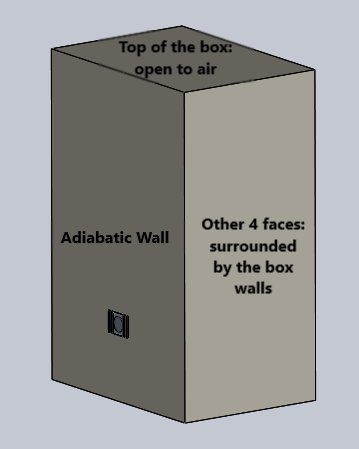
I guess the main problem is related to the boundary conditions. As the oil is not an “infinite” medium as the air and, actually, is surrounded by well-defined walls (the heat sink is submerged in a box filled with oil), I am not sure if I can set, for example, a pressure-inlet-outlet velocity boundary condition for all the lateral surfaces. And, even if I could, I guess the pressure value should be taken as dependent of the oil depth.
Is there anyone who has ever done something similar to this or has an idea of what can be done?