NACA0012 Stall Analysis

Analysing a Wing Section

When analysing a wing section, we are usually interested in these few things:

  • Coefficient of Lift
  • Coefficient of Drag
  • Most efficient angle of attack
  • Angle of stall
  • Stall characteristics

All this can be studied in CFD and is usually preferred over experimental studies as CFD tends to be less time consuming and easier to gather and analyse the information.

Stall Characteristics

It is recommended to start simple and build up when a good setup is achieved, however when high flow separation occurs (i.e. around and after the stall point) certain phenomenon’s will take place making your results inaccurate and sometimes stop convergence of a steady state simulation. The main reason for this is vortex shedding, experimental results would be taken when the flow was fully developed. If convergence is reached it is likely to converge at the point before vortex shedding. This means to analyse the stall characteristics you are likely to have to run a transient simulation, this is by nature very computationally expensive.

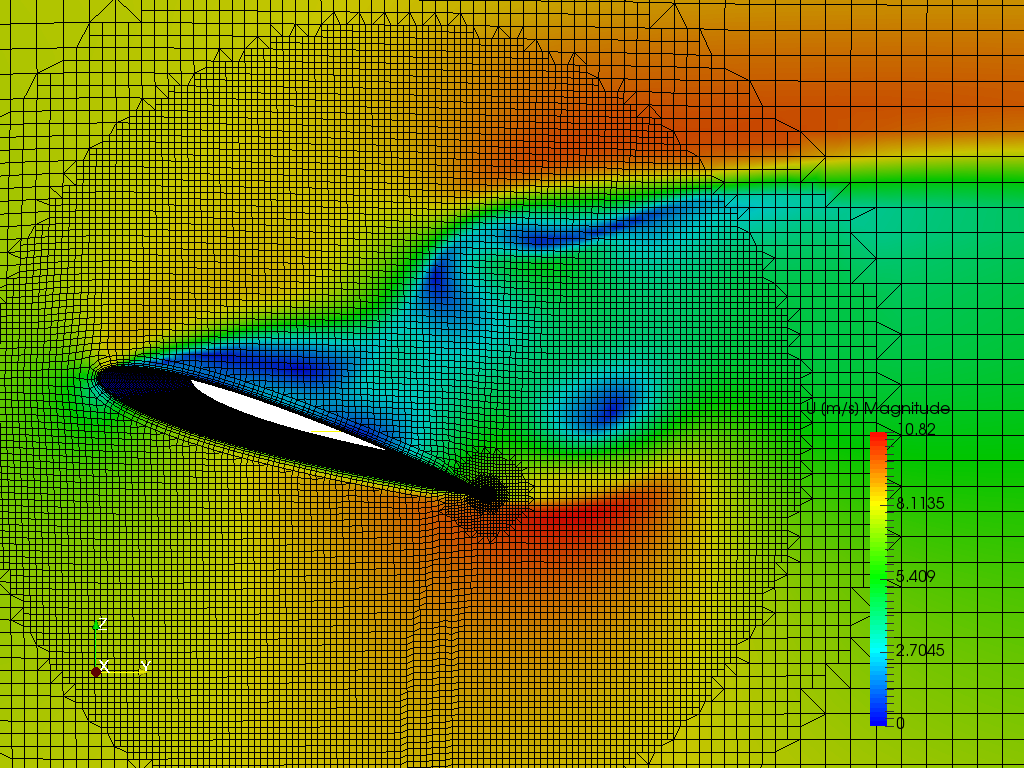
An unconverged steady state simulation after stall
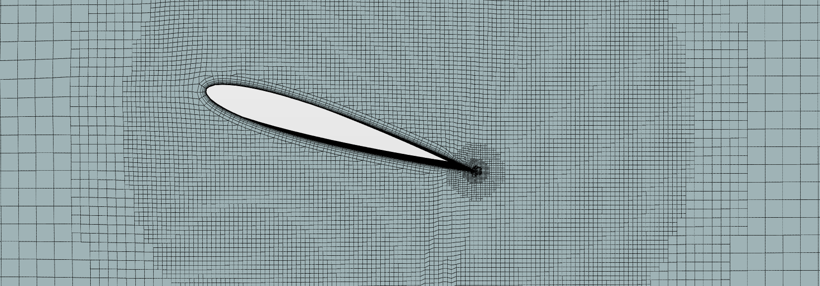
Setting Up a Mesh

here are two approaches that might be used when setting up a mesh in SimScale.

The first approach is best used when velocity is fairly low, a mesh can be generated to serve the analysis of the aerofoils at all angles of attack. This method involves importing the geometry at a zero angle of attack, creating sufficient mesh around the aerofoil to allow for varying flow directions. This way instead of varying the geometry and re-meshing we simply change the flow angle.

The second (the method I used in the RANS & LES comparison) is to vary the geometry and re-mesh with the same setting each time angle of attack changes, this seems a lot of work however at high velocities we can ramp the inlet velocity. There is also the advantage that the mesh will be aligned with the flow direction.

Setting up the simulation

This is a fairly simple setup, the only complications are the inlet/outlet boundary conditions, you can define these conditions as freestream velocity conditions or custom inlet-outlet velocity. The result control item Force Coefficients will need to be set and it also useful to set y+ control item as well to ensure the boundary layer has been sufficiently resolved.

Matlab code for quickly calculation velocity, lift and drag vectors

velocity = 97.1265;
angle = 17;

xVelocity = 0;
yVelocity = velocitycosd(angle);
zVelocity = velocity
sind(angle);

x_Lift_Direction = 0;
y_Lift_Direction = cosd(angle+90);
z_Lift_Direction = sind(angle+90);

x_Drag_Direction = 0;
y_Drag_Direction = cosd(angle);
z_Drag_Direction = sind(angle);

Velocity = [xVelocity,yVelocity,zVelocity]
Lift_Direction = [x_Lift_Direction,y_Lift_Direction,z_Lift_Direction]
Drag_Direction = [x_Drag_Direction,y_Drag_Direction,z_Drag_Direction]

Method of Gathering Data

Every angle of attack will need to be run to record the Coefficient of lift and drag if the aerofoil has a camber negative AoA’s might need to be run. The data can be visualised (using excel or Matlab) to easily show the characteristics of the aerofoil.

Matlab code for plotting data

%AoA , Cl, Cd
wingData=[0, 0.0840, 0.0193;
2, 0.2378, 0.0217;
4, 0.3905, 0.0300;
6, 0.5380, 0.0428;
8, 0.6753, 0.0635;
10, 0.7900, 0.0895;
12, 0.8773, 0.1240;
14, 0.9430, 0.1664;
16, 0.9882, 0.2161;
18, 1.0204, 0.2669;
20, 1.0286, 0.3178;
22, 1.0097, 0.3686;
24, 0.9925, 0.4148]

%Cl/Cd
wingData(:,4)=wingData(:,2)./wingData(:,3)

%Plot on 3 Graphs
figure

%Cl v AoA
subplot(1,3,1)
plot(wingData(:,1),wingData(:,2))
xlabel(‘Angle of Attack (degrees)’)
ylabel(‘Cl’)
grid on
grid minor

%Cd v AoA
subplot(1,3,2)
plot(wingData(:,1),wingData(:,3),‘r’)
xlabel(‘Angle of Attack (degrees)’)
ylabel(‘Cd’)
grid on
grid minor

%Cl/Cd v AoA
subplot(1,3,3)
plot(wingData(:,1),wingData(:,4),‘m’)
xlabel(‘Angle of Attack (degrees)’)
ylabel(‘Cl/Cd’)
grid on
grid minor

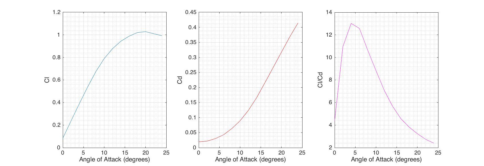
The above image shows information of the aerofoil characteristics mainly before stall, It also shows the most efficient angle of attack, this occurs when Cl/Cd is at its maximum.

could you do more airfoil simulation?

Hi @shrikant_patil, apologise I don’t quite understand. Do you mean more simulations of different aerofoils?

Thanks for your interest,
Darren

1 Like

yes, sir . I want to know how to do different airfoil simulation in different angle of attack and study about there stall condition.
If you know any book related airfoil section and there application please tell me.
Also if you know how to do in ANSYS fluent software please upload the link or give me some reference book

Ok, what I’ll do is write some information on how best to set up a simulation for running at different angles of attack. As for books, I like ‘Theory of Wing Sections’ by Abbott and Doenhoff. The reason I like this book is because there is lots of experimental data so it is good for checking your simulated results against. Although it occasionally goes a bit deep for what I need. The experimental data would also be a good quick look up to see the relation between types of stall and different wing sections.

I don’t use ansys a lot so I’m afraid I can’t help you much there.

Kind regards,
Darren

1 Like

Updated… I’ll keep adding to this.

Thank you… sir.

Sir I needed help regarding icing of NACA0012 airfoil , I am following this https://pdfs.semanticscholar.org/599e/78ee9196ce174d7ee2d021b88e7beb8986be.pdf


According to this I need to use Lewint LEWICE to do the same before simulation, how to I proceed ?

Is this type of icing simulation possible with Simscale?

Hi @dhruvism, unfortunately, I have never used LEWICE so I don’t really know how it works… Did a google search but was unable to find a download, do you know where I can get a copy?

Essentially if it generates a geometry from the using simulation and you need results from it then yes SimScale could run that external flow simulation but if you are asking if SimScale can do an icing simulation the answer is to my knowledge no. If we had phase change in multiphase flow the answer might have been different.

Looking forward to your reply,
Darren

Greetings Sir

I would like to thank you for taking time to reply.

  1. Regarding the software , LEWICE is used by NASA so you’d need special permission to access that. So there’s a free alternative to LEWICE which I found called LEWINT, but I’m not able to understand the interface so please help!.

It can be downloaded here

ftp://ftp.lightlink.com/pub/dparkins/incoming/LewRel/LewInt104.exe

(official site with file size of 199 mb)

  • According to this project , what is does that is basically inputs the CAD file and sets the conditions for icing and alters its geometry ( which I couldn’t understand) which can be made into a file and input for simulation.( this is where Simscale or Fluent comes into play I think)

  • Regarding my project , I need to include icing in the NACA0012 airfoil and perform simulation and compare it with a wind tunnel testing on a scaled down version of the model of wing.I am trying to recreate the thing mentioned in the following tutorial.

Project : [PDF] The performance of an iced aircraft wing | Semantic Scholar

(PS: The links I provided are completely safe and free for download)

Hi @dhruvism, I downloaded LEWICE I too was also a bit baffled by the user interface and the lack of a decent guide. From the project it looks like this is a very iterative approach, gaining CFD results calculating the ice build up and reiterating until we are happy with the results, just so I know is this a university project or are you looking for means of solving this problem?

Also to note if you are a commercial user then the LEWINT is just the GUI to LEWICE and therefore you do need a licence to use it after the 2 week trial.

Kind regards,
Darren

Yes Sir, I’m doing this for my university minor project , but I was also not able to understand how the LEWINT software works. They have a really poor tutorial. Anyways, thanks for your reply.

@sjoshi, can we do anything like this in simscale? I found the following paper:

looks like thin film propagation can be done in OpenFOAM, is there an iterative approach or something we can use in current implementation to do wing icing?

Cheers,
Darren

Hi @dhruvism got LEWINT working finally:

If you want I could write a bit in the above post about setting it up and getting a geometry together for analysis in simscale?

Kind regards,
Darren

1 Like

And if you want me to do this let me know roughly how long you want to run for and atmospheric conditions etc… I found these resources helpful:

CFD Simulations of an Airfoil With Leading Edge Ice Accretion

LEWICE 3.2.2 manual

Yes Sir , please do .I 'll be highly obliged
The input for this simulation
Flight height = 2400 m (8000 feet),
Air velocity = 66.7 m/s (130 KCAS)
Temperature = -5°C
Rain droplet size = 25 micrometer
Cloud liquid water content (LWC) of 0.5 g/m
Flight Time = 45 mins.
Ice shape formed= Horn type

Also mention the steps required for geometry creation and analysis using Simscale
Thanks in advance

1 Like

Hi @dhruvism, just one more thing is this 0 angle of attack? If I don’t here shortly I’ll presume 5 degrees AoA or something just for example :slight_smile:

Darren

Angle of Attack is not known , you can take 20 degrees

Hello there


Does anyone know or have the skin friction coefficient (Cf [-]) data for NACA 0012 airfoil between 0-10 degree Angle of attack at 4 million Re

even if the data is empirical or CFD simulation it is ok and for atlleast one angle of attack.


Any help is appreciated

Hi @vbhargava!

Does that help?

Source: http://what-when-how.com/wp-content/uploads/2011/07/tmp1A092.jpg


Best,

Jousef