I have been considering pitching SS to my work for some time now, but was looking for a strong case to support it first. Currently we use Solidworks with the simulation and flow packages.
I have a project that I know I cannot complete in Solidworks, but I’m also unsure if SS is capable yet either from the research I’ve done.
Here’s the rough breakdown:
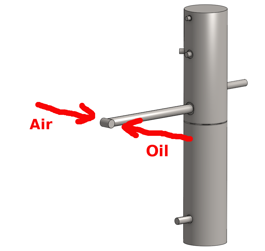
Sump is a stainless steel thin wall pressure vessel.
Roughly 3 ft tall by 6 in diameter
1.5 in inlet located mid-level
Two 0.5 in outlets on the side near the top and bottom
Inlet Condition:
200 F oil/air mixture
~0.03 gal/sec oil, 120 cfm air at 60 psi
Outlet Bottom
~0.03 gal/sec (assume just oil)
Outlet Top
60 psi (assume just air)
Initial Conditions
Sump has 1.5 gal of oil to start
Ambient air
Here’s the part that I’m not sure SS can handle.
I have to locate a temperature switch just outside the sump (access to the oil via a port, but cannot extend a probe into the sump space). From some testing we KNOW the added material for the port affects how quickly the switch is heated up, but have been unable to create any simulations.
Solidworks cannot do multi-phase, but can do fluid to solid thermal analysis. It seems that SS can do multi-phase but not the thermal.
It seems like quite an interesting project you described.
As far as I understood, the outcome of the analysis is to determine how do additional material placed on the wall of the sump between the oil and probe affects the measurement.
If this is the case, did you already try the full solid-state thermal analysis? You could model the presence of the hot oil by using a particular boundary condition type (on SimScale that would be Natural Convective Heat Transfer).
With this approach you significantly reduce the complexity of the problem and focus the area of interest.
When it comes to SimScale capabilities, at the moment these are the available simulation types:
solid state heat transfer (no fluid flow, though its presence can be modeled with proper boundary conditions)
convective heat transfer in single fluid (no solid heat transfer- though as above it can be modeled)
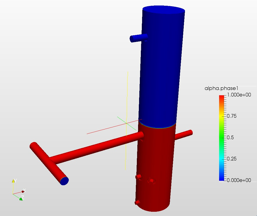
multiphase flow simulation with 2 non-mixing fluids (only fluid-fluid buoyancy, no thermal)
We are working on releasing soon a simulation model for solid-fluid thermal analysis (Conjugated Heat Transfer- CHT). With this upcoming feature you will be able to simulate thermal behavior of systems consisting of multiple solid domains and uniform fluid domains (so only one fluid for one domain).
Right now if you know that oil mixing at the bottom of the sump will modify the readings, you can first perform convective heat transfer single fluid simulation of oil, and apply the resulting boundary information to the solid-state thermal simulation.
To sum up- the full multi-physics simulation of oil particles injected with air to a solid container together with heat transfer in all domains is not available (and honesty speaking very few software are able to handle such complexity).
At the same time the problem can be solved with existing tools, by using modeling techniques.
so I took a look at your project - very interesting. So as @psosnowski described, the fully coupled multiphysics sim, including
Flow sim of both fluids
Fluid Heat transfer in both phases
Solid Heat transfer
But there might be a modeling strategy for this. I have not fully understood yet, what’s the crucial characteristic of the compressor sump, that you want to simulate? Is it how fast the steel pressure vessel heats up for the outside? Or how how the oil is that leaves the vessel? What’s the crucial metric you’re interested in - from there we can start modeling it back.
I’ll give the multiphase flow sim in the meantime a try, I did get it correctly, that it’s supposed to be standing “upright” and air and oil are entering that way, correct?
David,
Thanks for taking a look at this. The initial conditions are very close. The oil is actually below the inlets to start, but that’s an easy fix.
Ultimately on this setup I’m just looking at flow. The solid I uploaded is just the internal domain. I would need a second solid to represent the wall thickness on the walls and tubing for heat transfer correct?
The two side by side ports below the inlet are mounting locations for a temperature sensor (straight down) and a temperature switch (offset).
Questions being asked about this design:
One of our service techs believes the inrush of material is so fast we may be getting a dead zone over one of the temperature ports (Little to no oil actually touching the port due to a vortex effect)
When I do start looking at heat - One of our suppliers accidentally left too much material on the port that is offset which caused sensing errors. (Before steady state, you could grab onto the port with no difficulty while the side of the sump next to it would burn you) I would like to show this effect down the road.