Could anyone please help me with the information required to be inputted into the forces and moments field to correctly calculate lift and drag.
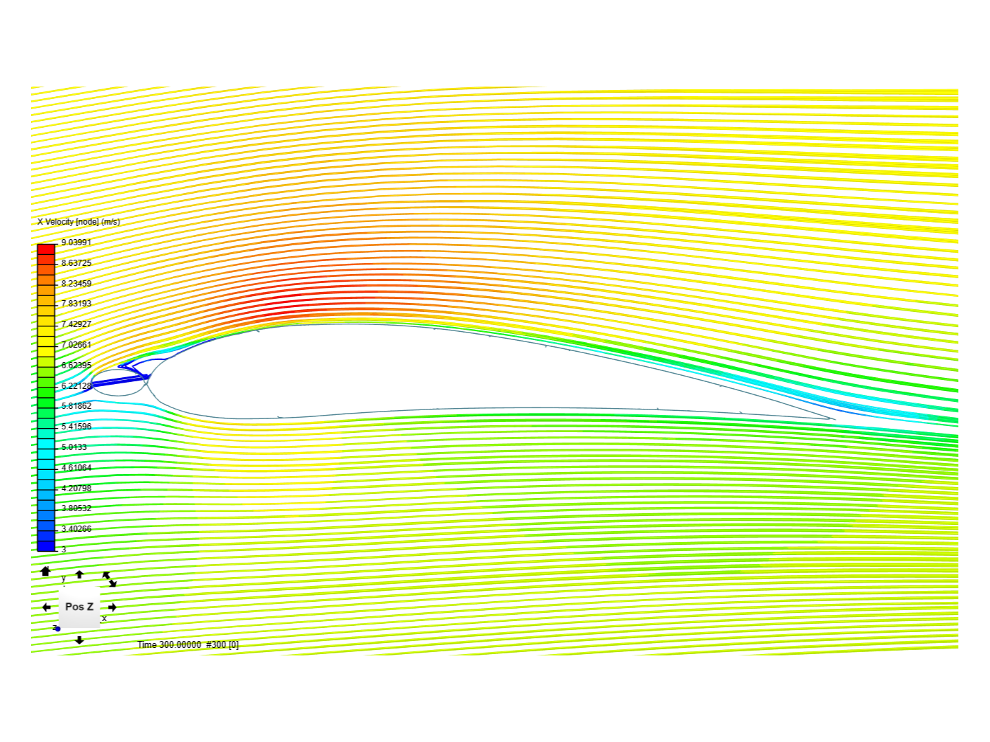
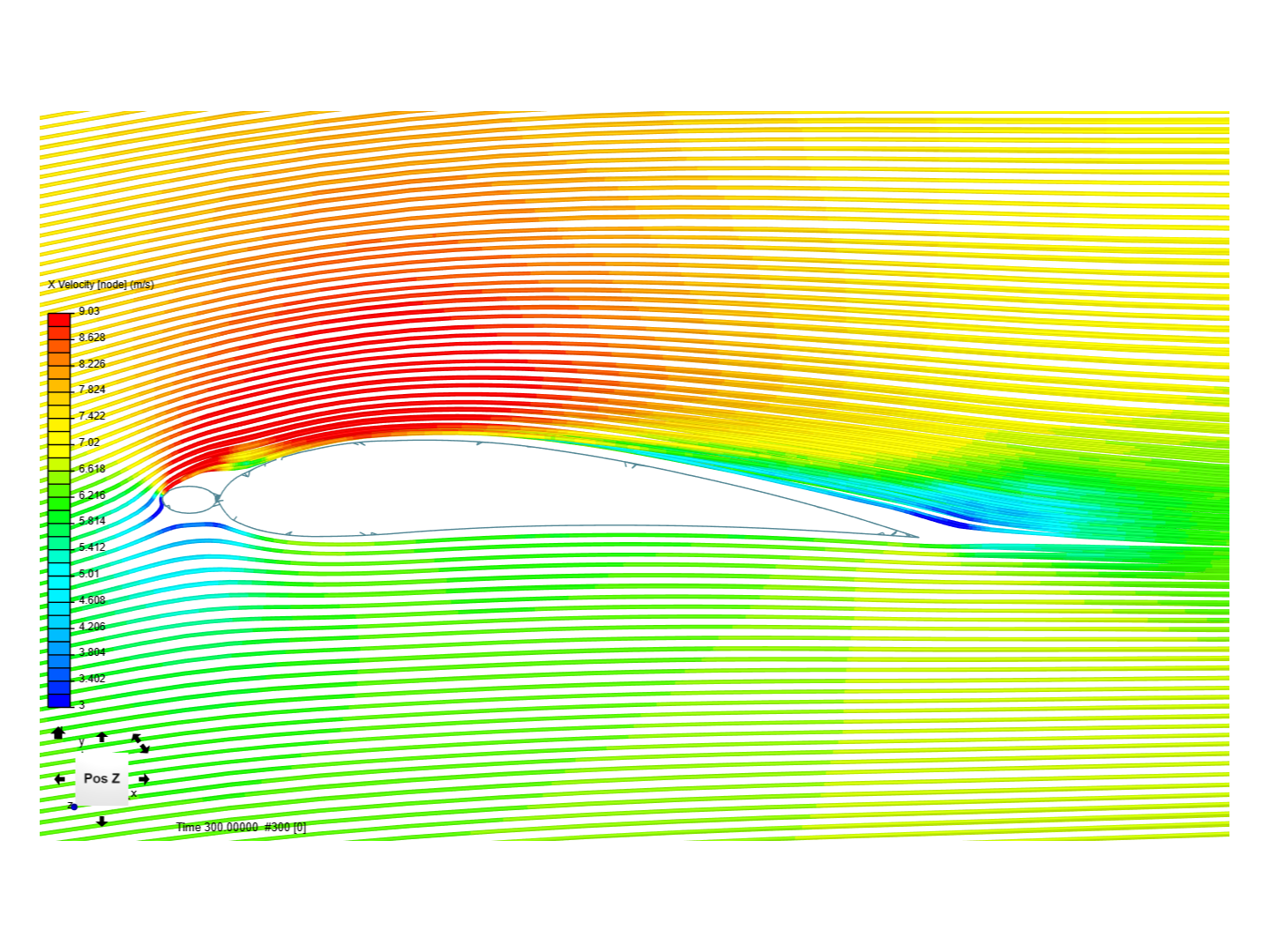
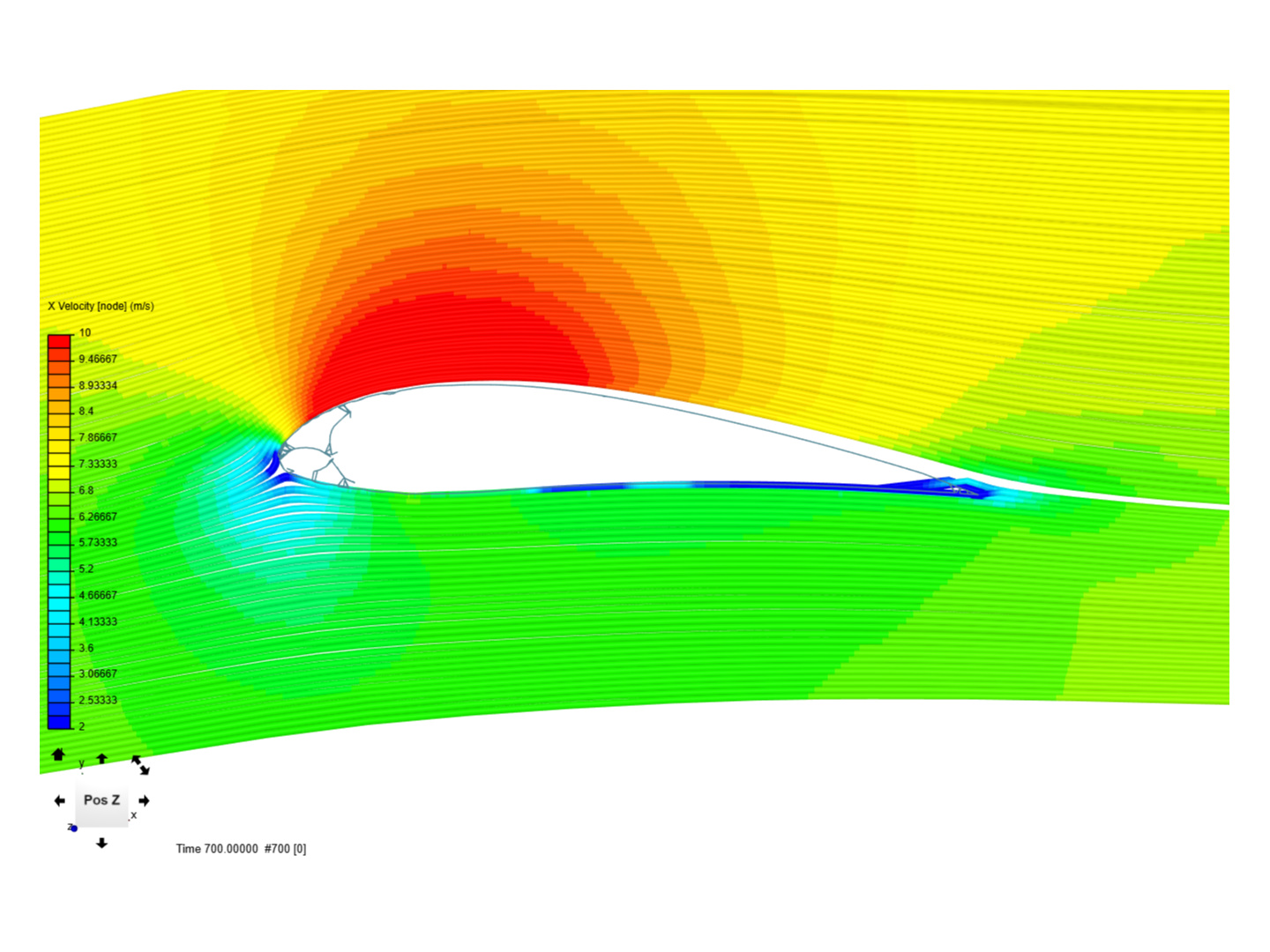
Below are 2 images of the same profile wing in 7m/s 7deg AoA, One is 2m long, the other is 8m long.
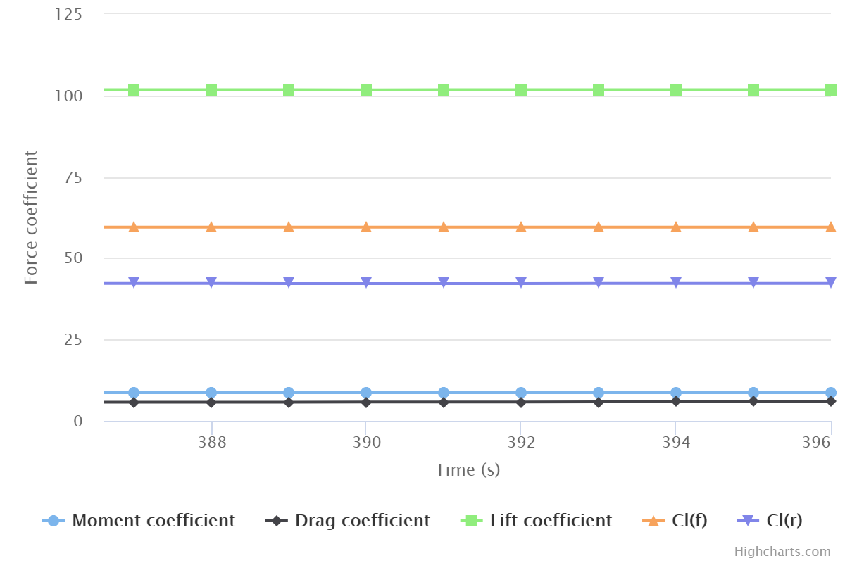
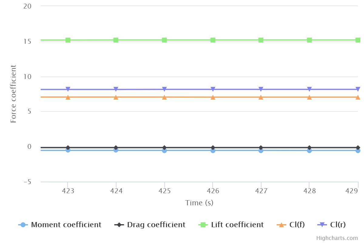
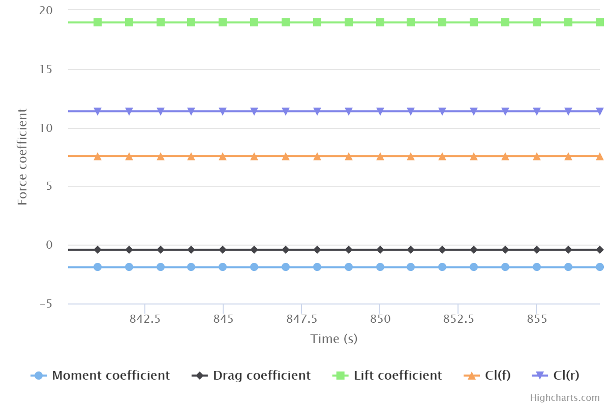
As per the X velocity (node) particle traces, they are satisfactorily the same. But the lift and drag co. are vastly different.
Do I need to add further data to the reference length and the reference area value?
Does the centre of rotation make any difference?
2m long wing and chart details
8m long wing and chart details.
Many thanks in advance.
Hi there!
Increase your bounding box domain size and make use of the “Potential foam initialization” under Simulation Control and let us know if there is a differene in the results, I assume there will be 
CFD Squad, could you add your two cents here also regarding the “Forces & Moments” result control item?
Cheers,
Jousef
Jousef,
thanks for you help.
i increased the boundaries, i believe all my figures are correct for inlets outlets etc. ( i use 2 inlets and 2 outlets, as i am changing the flow angle and not the model angle - but it does not make any difference) I am not sure what else to do for the moments and forces.
The following screen shots reveal good flow, expected velocity and pressures etc…
but still the drag coefficient is negative.
appreciate any further help.
I still do not think it is big enough, with big I mean something like this (can be a bit smaller though): SimScale - let us know how things go!
All the best,
Jousef