I am a (retired) engineer but a CFD newby.
The intention is to investigate and refine the design of a very small centrifugal pump (model IC engine coolant pump - 1/2 inch impeller diameter). The flow requrement has been established by back-of-an-envelope calculation and the pressure requirement by circuit flow experiments. The resulting 0.3 l/min at 1kPa give a non-dimensional specific speed of about 1, or Anderson’s ‘shape number’ about 1800, which would be close to optimal in a normal sized pump.
I have followed, as best I can, the steps in the tutorial Fluid Flow Through Centrifugal Pump | Tutorial | Simscale.
I have completed several successful runs with the ‘incompressible 2’ simulation. The results seem a bit weird, but suggested changes to the pump design.
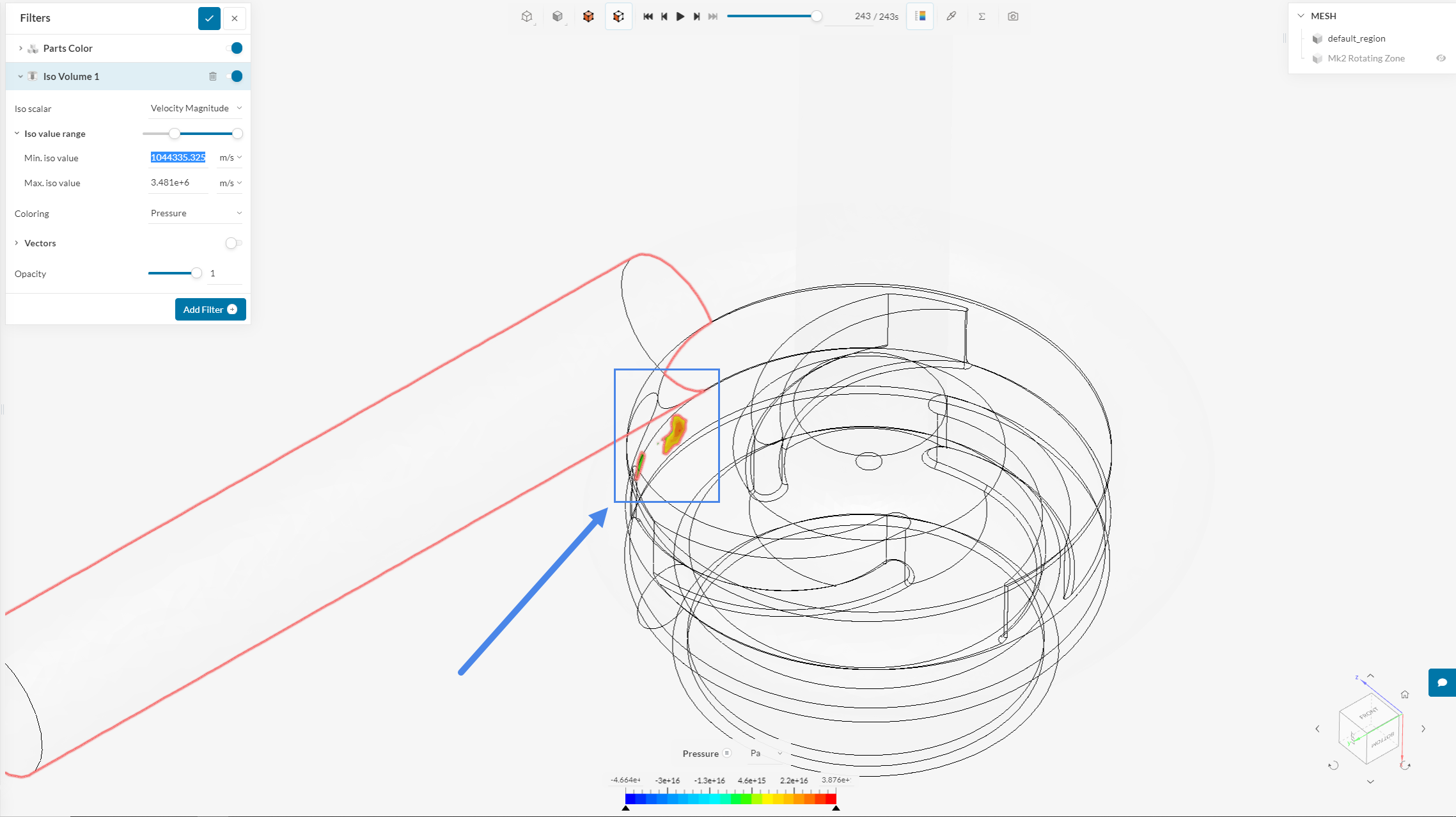
Simulation runs with a new ‘Mk 2’ design failed with divergence. The point of divergence appears to be at the root of an impeller blade, so a Mk 2.1 design has a radius at the blade root. A run with this model has also failed.
Other differences are a completely different (proper) volute, which is probably not relevant, and the fact that I have made the rotating volume much tighter to the impeller, so that it does not encompass static boundary surfaces.
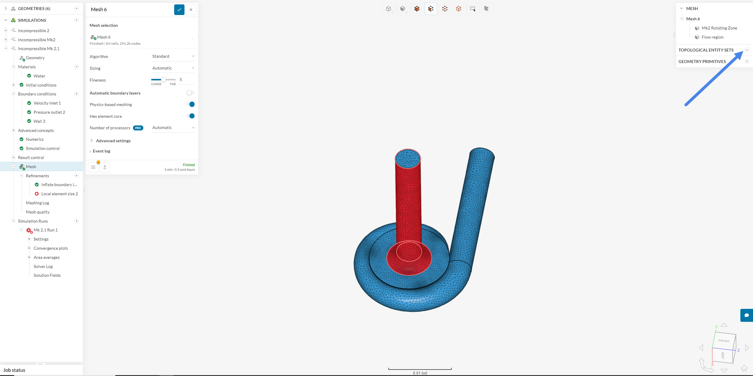
Looking at the mesh, it seems to me that it is already quite fine around the impeller blade roots, and I am not sure if going finer would help.
There were aspects of the tutorial I had trouble with following. It uses a couple of predefined topological entity sets - one for forces and moments on the impeller, and one for ‘local element size refinement’.
I am having trouble with creating these for my model. I created one for the impeller in the original Mk 2.1 geometry. But the second last step in editing in CAD mode is to delete everything but the flow volume and rotating zone, so the impeller entity set does not appear in the copy geometry created for simulation. I don’t understand how to do this.
I probably also need ‘local element size refinement’ as there are some narrow clearances, particularly beween the impeller and the inlet cover flange. Again, I don’t know how to do this.
Apart from help with these issues that I am aware of, I would be most grateful if someone could do a general sanity check. With these very small dimensions, viscosity and friction are particularly important, and I don’t know if that affects how the model should be set up. (I have varied the viscosity and density from ‘standard’ water, as in this case it is hot.)