I stumbled across this tip the other day and thought I would share it, as it may be helpful to others.
I use Solidworks for modelling and regularly use the geometry “Check” feature to check for potential problem geometry (especially short edges).
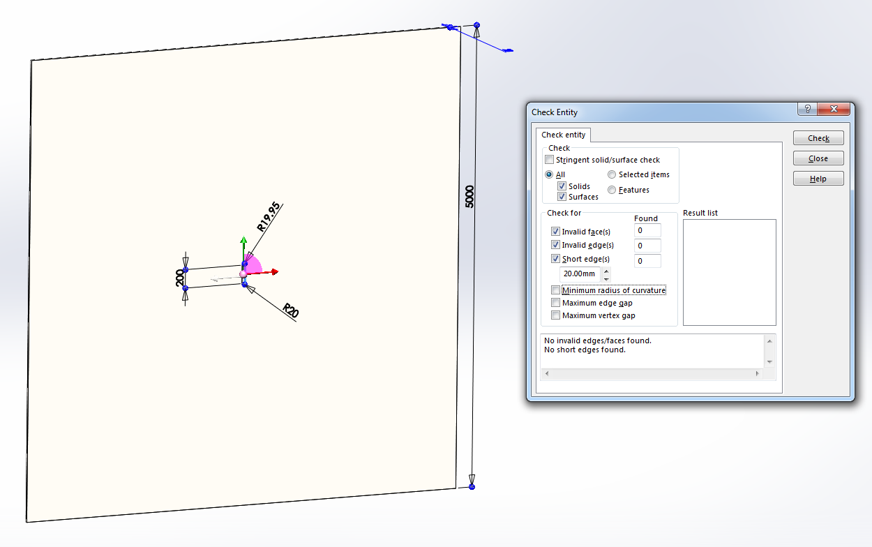
Here is an example of a model that passes the geometry check. There are no edges in this model shorter than 20 mm and it longest edge is 5000 mm. So it’s shortest edge is only 1/250th of its longest edge. I would expect this model to mesh with no problems.
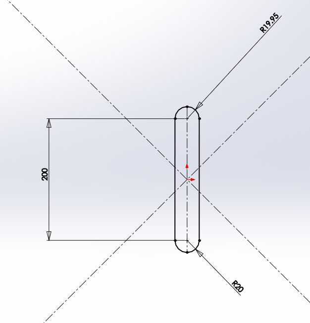
Here is a closer view of the slot in the middle of the plate. Note that the top and bottom ends of the slot are slightly different sizes.
The “fully automatic tetrahedraliztion”" fails on this seemingly simple geometry. Why?
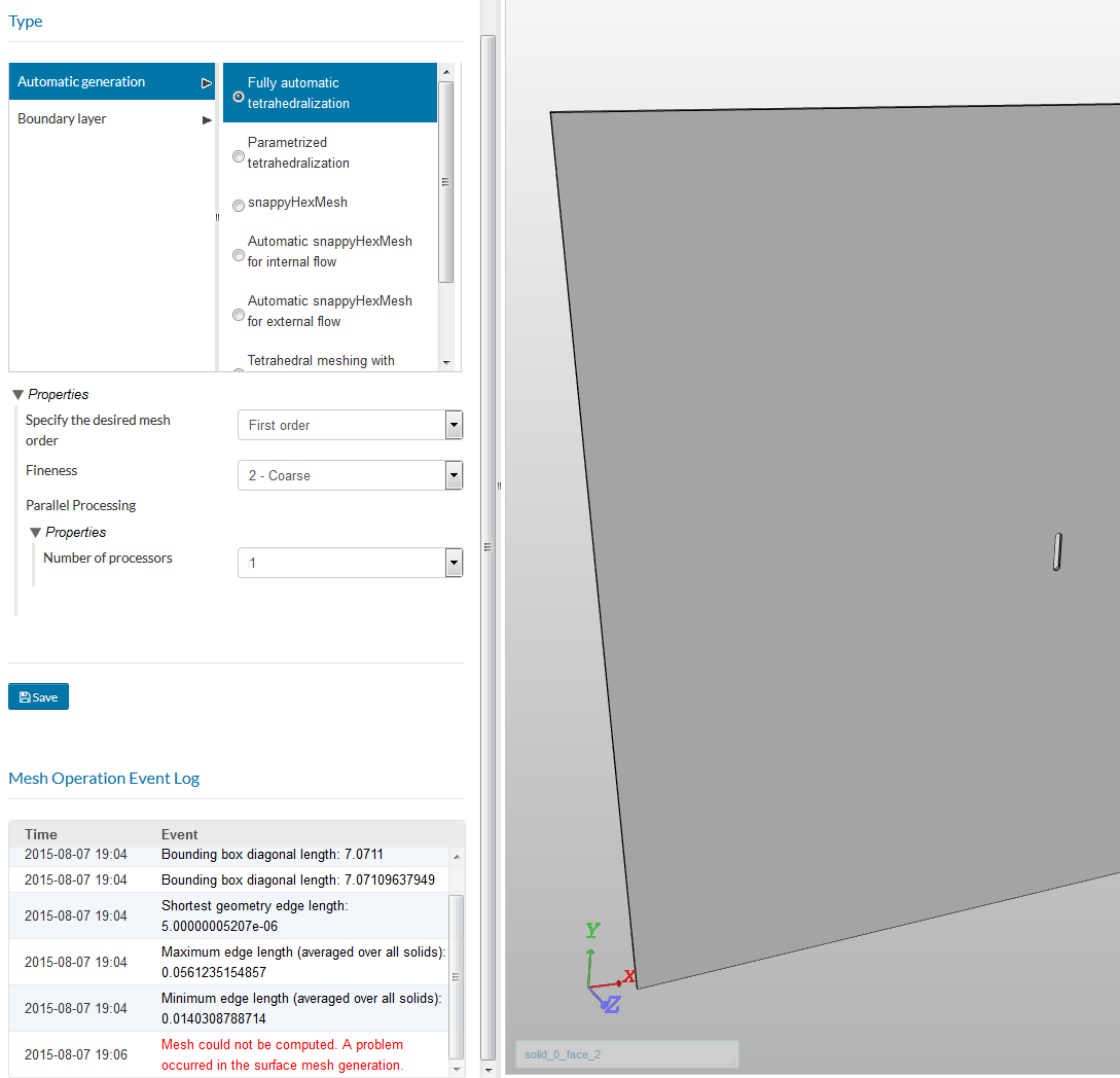
The error reported in the SimScale event log is…
“Mesh could not be computed. A problem occurred in the surface mesh generation.”
But there is a clue listed earlier. SimScale reports the smallest edge being 0.005 mm ,which is much smaller than the expected 20 mm.
It turns out that the short edge is introduced in the STEP file conversion.
In Solidworks there is a STEP export option to “split periodic faces”. When enabled, all cylindrical faces that wrap more than a certain amount (180 degrees I think) are split into smaller faces.
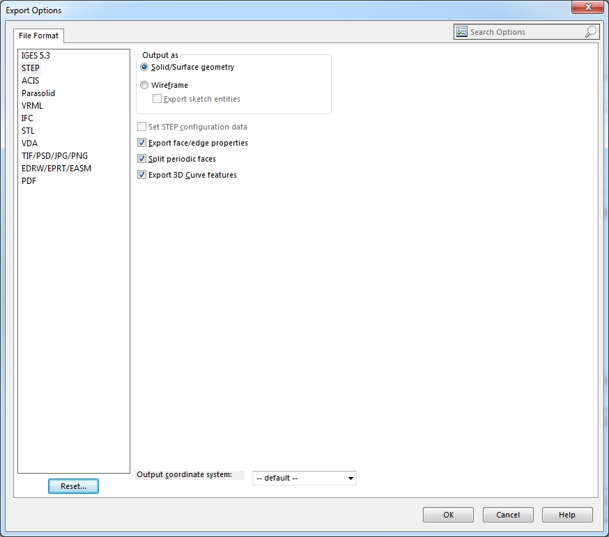
In the example, because the top and bottom rounds of the slot are slightly different sizes, the bottom face wraps slightly more than 180 degrees. In the export, the bottom cylindrical face of the slot is split creating a very small sliver face where the bottom radius meets the vertical sides.
To make matters more interesting Solidworks does not show the sliver face on the exported geometry and the geometry check does not pick it up either. It is, however, visible in the SimScale model viewer.

Disabling the “split periodic faces” option solves this problem and the geometry meshes as expected.
Split faces are used to improve the accuracy of geometry, so there may be times when it is advantageous to enable the “split periodic faces option”. For example, a shaft in a bearing. In this case the problem face in this example would need to be split manually at a more logical location.