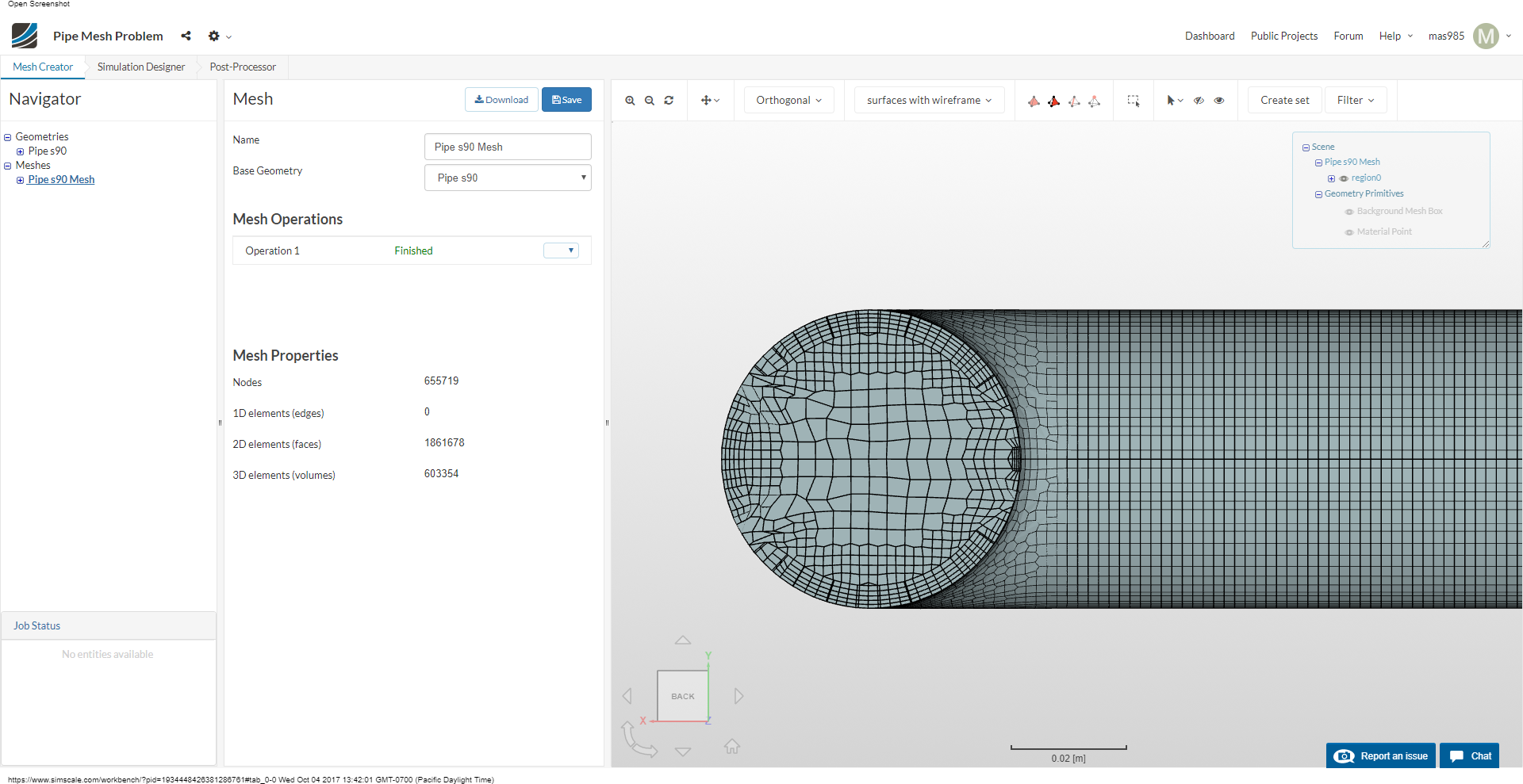
I am having difficulty getting a good looking mesh at the ends of a pipe in this project:
The mesh has an inflate layer region and a surface refinement. The inflate layer region seems to be removed/deformed in some parts:
Thanks
Hi again @mas985!
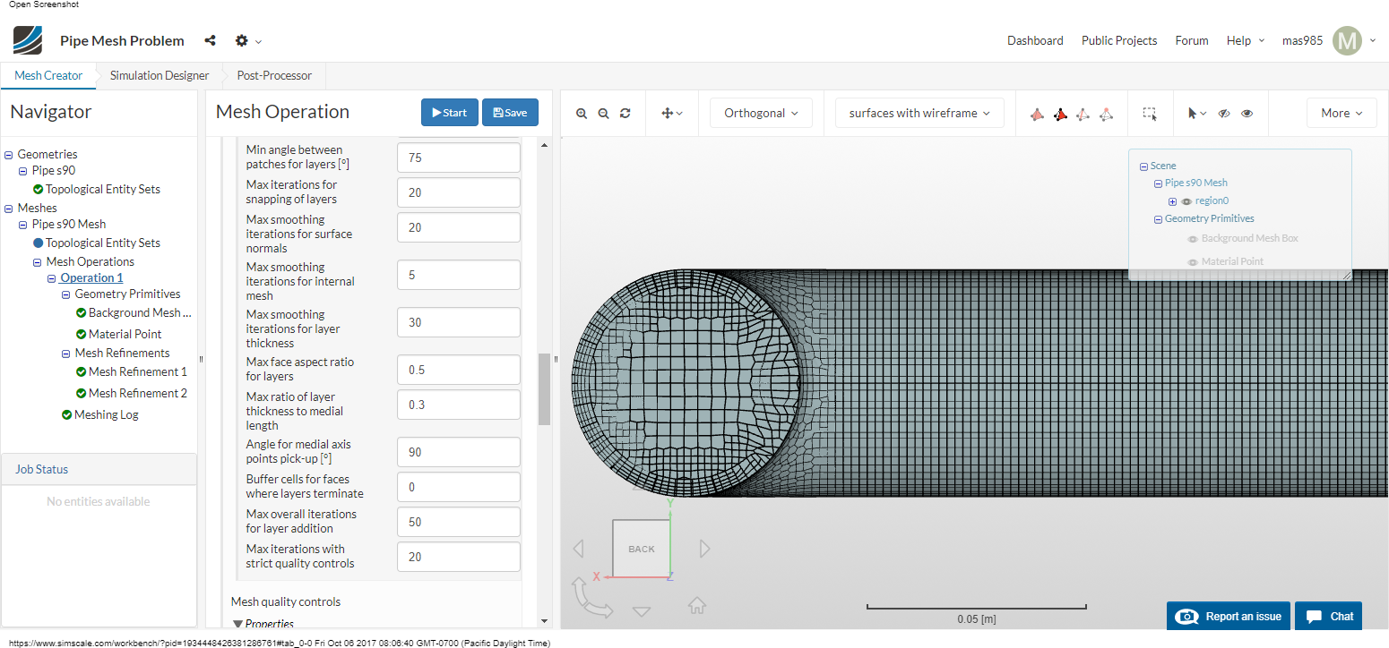
In your case it would help to modify the layer addition settings (mostly, the number of iterations).
Can you please try the following settings and tell me if that worked out for you:
All the best!
Jousef
Hey @mas985!
Having a look at it at the moment. Let me test some settings and get back to you later on.
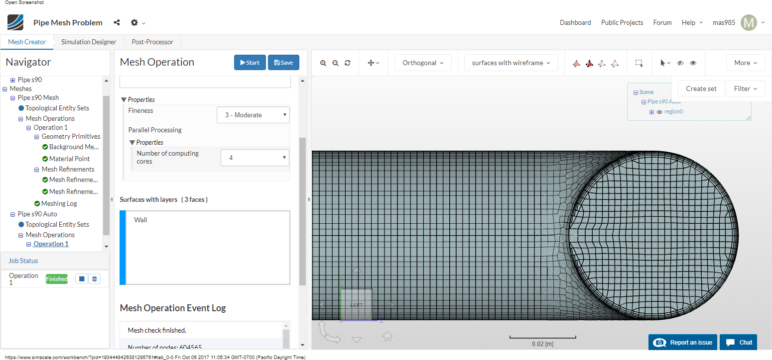
I guess the automatic meshes is not an option for you as you want to try how the parametric one behaves, right? Just for the sake of testing your simulation until I have figured out a good solution.
Best,
Jousef
The parametric is required so I get the correct y+ for the wall functions. Otherwise, I would use the automatic as it does produce a better looking mesh but the wall cell has a y+ around 15. It just doesn’t have the wall cell size control needed. Having an automatic mesh with a wall cell y+ target would be a huge feature in my mind. 
I may try a sim anyway with the auto mesh and just see how it performs.
Thanks a lot for the feedback @mas985!
Having a closer look and will let you know how we can fix this. 
Best,
Jousef
Has there been any progress regarding this issue?
Checking the status later on @mas985! Will keep you informed.
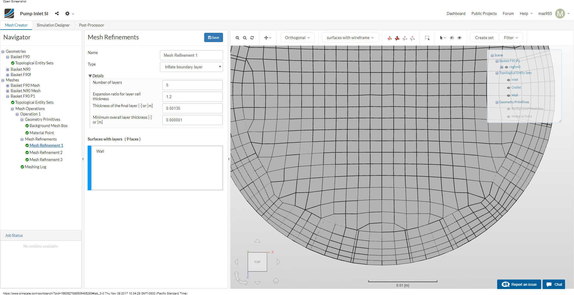
I re-meshed here, the problem was the refinement level. Because you are using non-relative layering it can be hard to create a layer which doesn’t inflict upon the aspect ratio quality control, however, refining means that the thin cells are shorter and thus aspect ratio is smaller, falling within the quality requirements.
If you look at the mesh (clip) you should now see a well-inflated boundary layer all the way to the ends.
Hope this helps,
Darren
Thanks!
It looks like there were changes to not only the quality controls but to the layer additions as well. What was the underlying methodology you used to come up with the changes or was it just trial and error?
I have been trying to get the same thing to work for a surface refinement level of 2 to keep the mesh size smaller but no luck. I think I probably need to spend some more time on what these advanced parameters do and the effects they cause.
Is there a way to prevent the mesher from moving mesh points and only allow removal or adding/splitting of cells?
Hi @mas985,
you could try changing the max aspect ratio option under layering that might mesh better but if any flow separates at the elbow high aspect ratio cells might cause instability if the flow isn’t flowing along them. But absolutely worth a try! I adjusted the quality controls as my first iteration which improved the quality but actually increased cancelling at the end.
Kind regards,
Darren
So I tried something a little different. I used all of the default advanced inputs and I then scaled all the base mesh cell quantities by 9/8. So basically, it shrank and shifted the base cells every so slightly and the result looks pretty good for refinement level 2.
My suspicion is that when there is an asymmetry in the base cells across the cylinder, it is more difficult to “fit” the layering in without changing the cell structure significantly. By shrinking/shifting the cells every so slightly, the fit is much better.
I have one more follow up question.
Is it possible to prevent the layer inflation from changing the cell width within the cell layers? This is critical for y+ management but the mesher seems to adjust the cell width throughout the layers. I assume this is done because of the internal cells. But if I want those cells to be an exact normal width (i.e. not adjusted), how does one go about doing that?
Hi @mas985, do you mean you want to inflate say 5 cells all with the same width? couldn’t you just reduce the expansion ratio to 1? or is that not what you mean? maybe a few illustration photos 
Best regards,
Darren
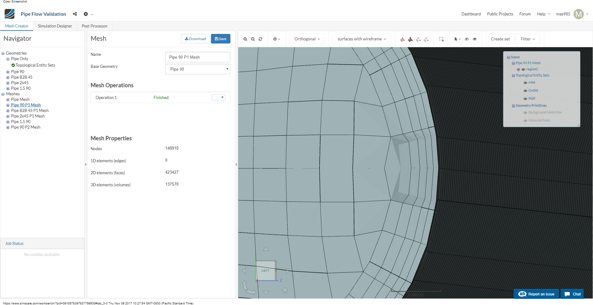
So what I mean is that if I specify the parameter “Thickness of the final layer [-] or [m]” in absolute meters, after meshing, it appears that this is a loose requirement and the result is sometimes changed to a usually smaller value. This changes all of the rest of the layers as well. You can see that here at about 3 o’clock:
Here is a better example at 5 & 7 o’clock
Ok I see, have you tried increasing ‘Max Smoothing Iterations for Surface Normals’? How critical are you finding this for Y+ value? is it actually pushing you out of the recommended range?
Kind regards,
Darren
No I haven’t tried that but I will.
As for the y+, I have set the the cell wall thickness for a y+ of 35 and then calculated the resulting “Final Layer”. So any reduction would push it to a smaller value and perhaps out of range. I could increase the Final Layer to account for this reduction but I am perhaps more interested in why it is doing this and how to prevent it from happening.
Ok, yer I understand. Well, let me know if that setting helped.
Cheers,
Darren