I am having issues in meshing this, I tried almost everything possible, cleaned up the geometry as much as I could, but still have problems in meshing the body. Could someone please tell me what more should I change so that the body doesn’t throw meshing errors?
I am trying to simulate how the pressure affects the interior of the manifold, it will be an equally distributed pressure on the inner faces of the manifold with the bottom and the side faces constrained.
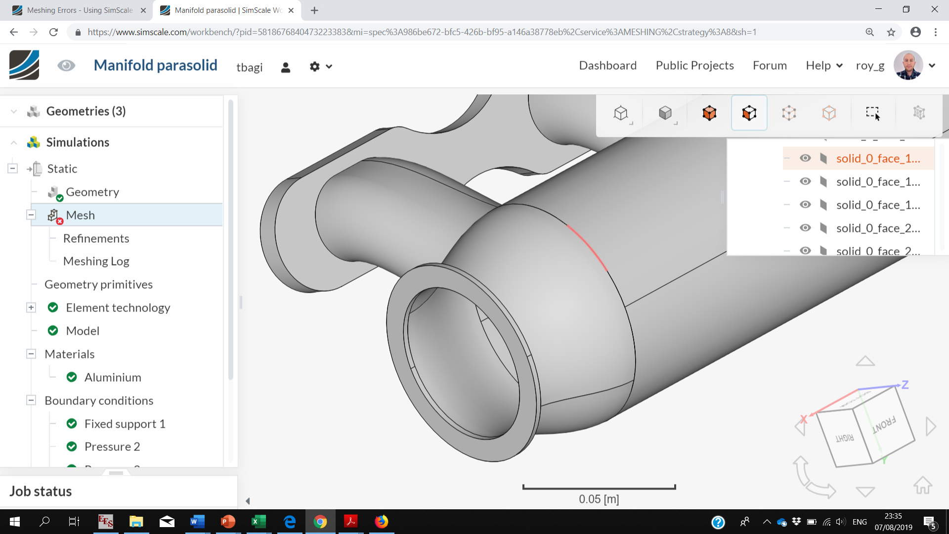
I looked for the surfaces that could not be meshed and look what I found, an internal surface in a single body (see the pink line in the image). It should not be like that. You have a problem with your CAD, perhaps gaps between the parts? Upload it and I can take a look. You may want to also simplify the part otherwise it will require a very detailed mesh. For example, the 4 very small ports seem totally unnecessary for this study.
I am not able to upload the CAD file here, where do I upload it?
I tried removing the pink lines you pointed out, but I was not able to figure out how to remove it. It is something very small. I will get rid of those 4 ports and upload the CAD.
Oh I see it is images only that can be uploaded. How about setup a free dropbox account (if you don’t already have one) and share a download link with us. I believe you can do the same with google drive as well.
Edit: Whilst it’s good that you are removing the 4 small ports, it will only make your model less resource heavy. It’s not going to fix your problem.
Although the problem planes show us, I can not see any visible issue. How did you make the main cylinder. Was it in a single step using the revolve function?
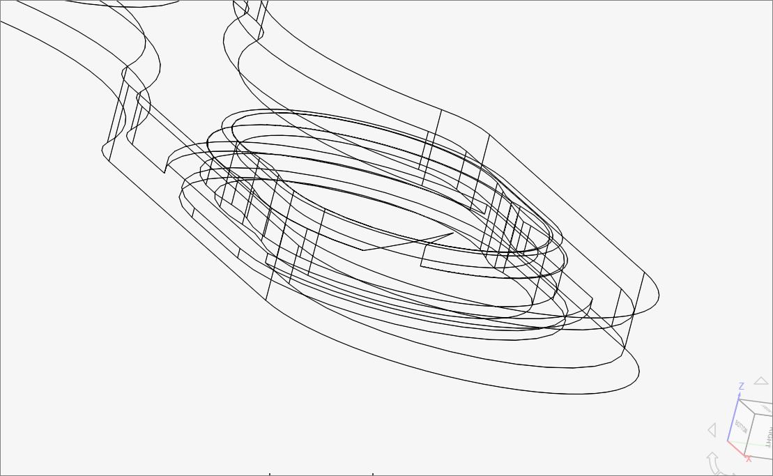
You’ve got some really weird things going on in that manifold.
Each bent port tube seems to be 3 surfaces instead of 2.
Your 4 port flange also has some weird internal surfaces.
I see over 100 unjoined edges.
You need to get this down to one watertight solid, either a solid 3D part that you can extract a fluid volume from or a single surface watertight solid that you can do an internal mesh on.
And then you pieced the rest together? Try making the entire main part including the closed end and flange in a singe revolve. Make the CAD part in the simplest way.
When I first looked at your project you have chosen the solid mechanics module, now that Dale speaks about it you should definitely make sure not to use multi-layered geometry and close every inlet and outlet face to make sure it is watertight (as mentioned by Dale already) and then just choose the according flow type simulation.
I do not intent to do a CFD analysis of the flow. I am simulating an evenly distributed pressure on the interior of the manifold. Do I still need a watertight geometry for this type of simulation?
Ah, I did not see that it was a static simulation, I just assumed it was for flow analysis, dah.
I any case all my CAD comments should still be valid except for making a ‘single surface watertight solid that you can do an internal mesh on’, which is valid only for flow analysis and of course you would not need to do the extraction of a fluid volume unless you want flow analysis…