I’m trying to mesh a model, but it had been running for a long time yesterday, and today it seems that it was so large that it wasted all my core hours, before stoping. Is there something wrong in what i’m doing?
I’m referring to my last 4 geometries, and last 4 simulations.
First of all, can you let us know what you want to simulate, pressure loss investigation for different geometries? The “threads” that you have inside of your geometry might be the cause of the exorbitant high meshing times. Also I see all your “horizontal” geometries have problems with meshing, there’s also an overlap between the objects as you can see at the corners.
Can you try the other mesher to see if there are any changes? But only after you made adaptions to your geometry, or are the threads essential for your investigations?
Im trying to simulate pressure distribution on the faces of the members as wind flows past the structure. The threads you’re seeing are what im using to achieve a ‘permeable’ surface of known permeability, being 10%, 20% etc., as the idea is that i’m testing the performance of cladding that would allow varying amounts of air to flow through it. I originally wanted achieve this permeability using holes, as in the geometry ‘Squares 1m 10%’, but the Acad file was around 100mb, and the subsequent STEP file 289mb. In order to reduce this size, I reverted to using strips instead of holes, as can be seen in the last 3 geometries.
Can you make sure to set the project to public ? Will have a look at it then - and good job on splitting the project as this will improve loading time for you (but also the support having a look at your project) significantly.
Ping me once you have changed the project setting.
I have chosen to use Standard meshing, because the file in question was taking too long using Hex-dom. meshing. However I cannot find how to create the outer boundary volume, and then assign the boundary conditions.
Sim in question is “Horizontal 1m 20%” using geometry “H1 20%”
@Ricardopg, could you have a look at that. I believe Mike wants to have other BCs as well in the first place as the air should move through the tube and not perpendicular through the domain?!
Already sent a link to the multi-region mesh issue.
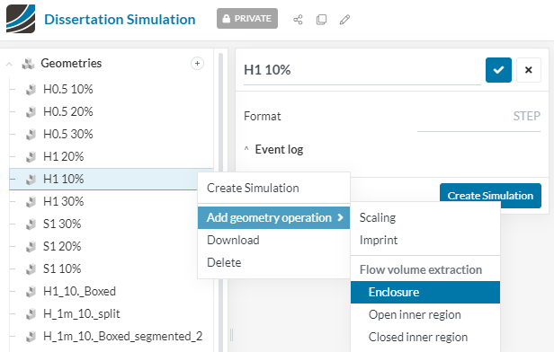
This is what I am trying to achieve; the mentioned geometry, with standard meshing, having wind flow from one boundary face to the other, impacting the structure. The structure I mentioned is similar to this in the picture, but with gaps in the outer skin, and a simple cuboid inside. I’m using standard meshing as Hex meshing was taking so long, and using up too many of my CHs. However once I carried out the Standard mesh, I was not able to assign the conditions I require, as I used to, to my Hex-dom geometry.
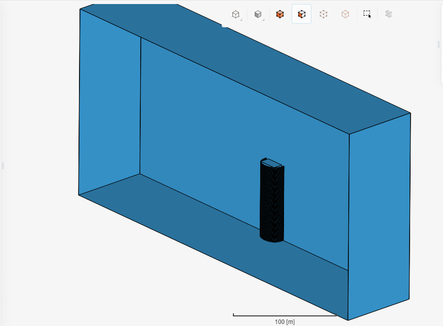
Since your geometry looks symmetrical, you can even consider just capturing half of it and applying a symmetry BC. After the enclosure operation, it would look something like this:
Let us know how well the standard mesher can deal with this geometry (and also some of the other more complex geometries, such as the ones with square holes).
By the way, I tried to mesh half of a geometry with square holes using hex parametric and couldn’t really do much. Even selecting faces for the refinements made my notebook freeze (it has around 28k faces in total)
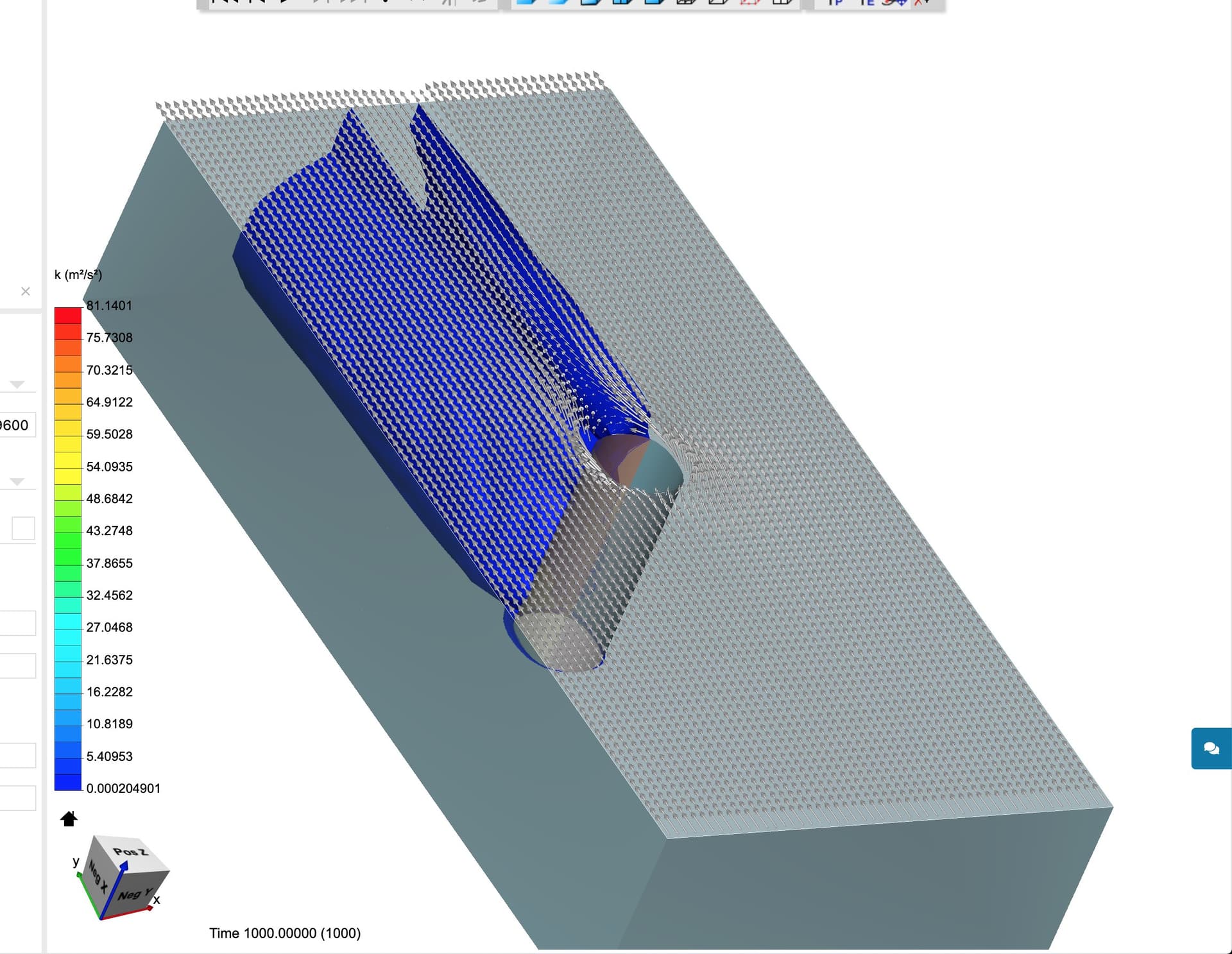
I have since tried this, but for some reasons the results weren’t as expected. I have a test model that I compare results to, that I had ran using the Hex-dom mesher. Whilst I dont expect the results to be exactly the same, I expect the direction to be similar. For some reason, the wind velocity was not running through the flow volume in the same manner as the image I had previously uploaded here. This meant there was something wrong with the enclosure or settings. I had exhausted all options in trying to fix this and still did not come to a conclusion regarding what the issue was. I had assigned the enclosure walls, the same boundaries that I had applied to the Geometry Primitive Box used in Hex meshing, and the wind instead of flowing as shown above, seemed to immediately twist and turn, making for a useless simulation.
I’m now just trying to push on with the Hex meshing on my complex model with square holes, in the hope it will ultimately work. I added the symmetry feature to speed up the meshing, which seems to have worked, but I’m not sure if it will be interpreted correctly when it comes to the simulation, which I am about to try.
In case you waned to have a look, the Sim I was referring to that showed wind flow unlike I was expecting is named “Plain Standard”, and the one I said I am pushing on with is called “S1 10% Split” both in the following project:
I would recommend that you start with a section in the middle of the height of your building that is only a couple slats/square holes high…
Use slip walls on the top and bottom of that building slice, that way your # cells in mesh could be reasonable for testing slat design… (worry about ground and top of building flow later)…
No need for new geometry, just move the top and bottom BMB surface towards the center of the building and put them each in the middle of a slat, encompassing 1 (or) two slats…
Thanks for you suggestion, this is what I have gone on to do. I had already modelled the 10m high model (instead of the 80m) and popped that into the sim, making all walls around Slip walls, but somehow the wind direction is not coming as I expected. Would you mind having a look to see if there is anything particularly wrong?
If you look at the post processing results of the simulation “S1 5% 10m” you’ll see this. I believe all the conditions are correct, as I had modelled very similar things for other simulations.
 Will have a look at it then - and good job on splitting the project as this will improve loading time for you (but also the support having a look at your project) significantly.