Hi, I am trying to run compressible flow simulations over different NACA airfoils.
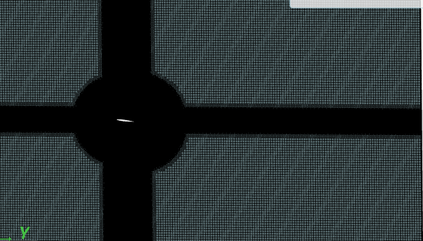
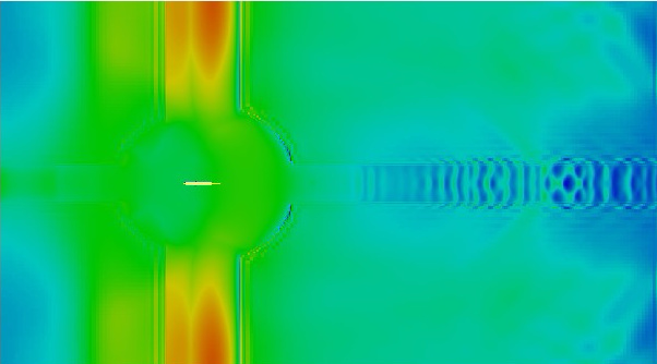
I have been able to run the tutorial “Compressible flow over airfoil” for the speed range I need, which is 223 m/s (M 0.65), but when I try to run the simulations for the geometries I have with meshes created using SimScale the data achieved is completely wrong due to you can see the outlines of the different cell refinements of the mesh in the post processor (I attach two screenshots, one of the pressure field and one of the mesh, but as happens in the pressure field happen the same for the temperature a speed field).
Therefore as it is a problem with the meshes (I tried different ones with same results) can someone explain me how to create the mesh used in the tutorial?
The project I am working on it is call “final project compressible” and it is in my dashboard (atalavera_diez). I have create different simulations and I also check if the meshes works for incompressible flow conditions (their work). The pictures are taken from the simulation “NACA0012 0 → NACA0012 0 c”. Also the link for the project is https://www.simscale.com/workbench/?pid=5352451548804250842#tab_1-0
Hi @atalavera_diez,
I will have a look at that later on. Tagging @1318980 here. He has done quite a few simulations with NACA profiles.
Best,
Jousef
Hi again @atalavera_diez,
just to give you some feedback regarding your project:
-
I would suggest increasing the domain size vertically and have the mesh refinement more in the area of the pressure fronts.
-
Please change your name convention if it is possible because it is hard for me to know what your names mean.
-
Try reducing the mesh size and go back to steady-state to ensure that that works before jumping into a high cell count transient simulation.
P.S.: Are you talking about the CFD Master Class - Session 1 ? The step-by-step instruction is very good and you should be on the right track using it.
Cheers,
Jousef
Hi @atalavera_diez, Just something I just noticed, the top and bottom are symmetry. I would call these ‘wall’, ‘no-slip’… This could be the cause of your troubles thinking about it, symmetry implies that there is a symmetric aerofoil above and below it. You could try an inlet-outled boundary condition on the inlet, outlet and the top and bottom, this helps reduce wall interference by allowing the fluid in and out of all sides other than the sides of the domain (which I would define as symmetry).
Hopefully, this clears it up a bit, let me know how it goes.
Kind regards,
Darren
Hi @jousefm,
I am going to follow your advice and see what happen. Also regarding to your feedback:
The name of the simulations are the profile (NACA0012) the AoA and later a “c” if I run a compressible simulation or an “i” if I run a incompressible simulation. If there are more than one with the same name I have add numbers after the letter just to difference the simulations that’s because I had run the case with different meshes or changing parameters in “numerics” or in “simulation control”
Respect to the steady state, I run the case in transient because when I run the tutorial, I try to run it for steady state cases but it give me all the times an error that say that the maximun number of iterations was exceeded here is the link of this other projetc. One of the possible solutions will be to ramp the values of the velocity with a table, but when I upload the csv file it give my this error:
“Cannot fetch results. Not enough data available in the processed CSV-file. Either you specified a wrong separator or less than two columns are available in the CSV-file.
Error code hcsf22xr”
P.S.: I was talking about the tutorial I add in the link before, but the one you say looks interesting thank you.
Regards
Alfonso
Hi @1318980,
What you mean with an inlet-outlet boundary condition? I know that in other programs there are this option, but in the boundary condition’s type didn’t appear this option in simscale.
Regards
Alfonso
Hi @atalavera_diez, If you navigate to custom boundary condition you can select the velocity as inlet-outlet further to this you will need to specify the conditions for the other required information such as turbulence variables and pressure. I think there is some information in one of the workshops about inlet-outlet boundaries but I can’t seem to find the right one, maybe @jousefm know the one I’m talking about?
Kind regards,
Darren
Hi, @jousefm,
I had try tu run the CFD MASTER Class - Session 1 with one of my geometries (also a NACA 0012 but the orientation of the geometry is different) and i achieve this error:
“The job execution was aborted, possibly due to a numerical instability. Review the log to identify reasons: unphysically large field values, extremely small time step size, etc. Modifying numerical settings and time step size could resolve the issue.”
Did you know which can be the reason? The simulation is in here, the NACA0012 tutorial layer.
Also @1318980 i am running one simulation with you advice of the boundary condition inlet-outlet, I will let you know the result when it finish.
Kind regards
Alfonso
Hi @atalavera_diez,
just wanted to let you know that we did not forget you 
We will get back to you as soon as we have a solution.
Regards,
Jousef
Thanks @jousefm,
I didn’t say anything yet because the simulations hadn’t finished, I am now working with a mesh without cartesian boxes or cylinders and in the boundary conditions with the inlet-outlet condition that look like it eliminate the problem of the mesh. When the simulations finish i will let you know the result.
Regards
Alfonso
Hi again @jousefm and @1318980,
Looks like that with a simple mesh (without adding geometry primitives, just refinements around the profile) and with the inlet-outlet condition the problem is fixed, the simulations take too long but the data looks better. The values of the force coefficients are higher than expected but that is another problem.
Thank you very much for your help.
Kind regard
Alfonso