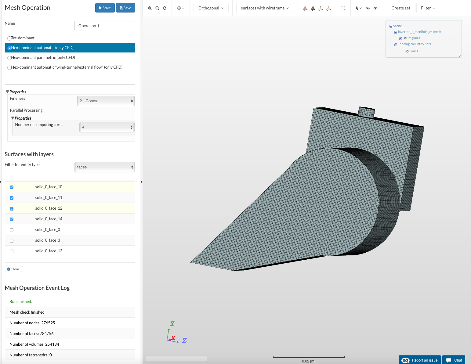
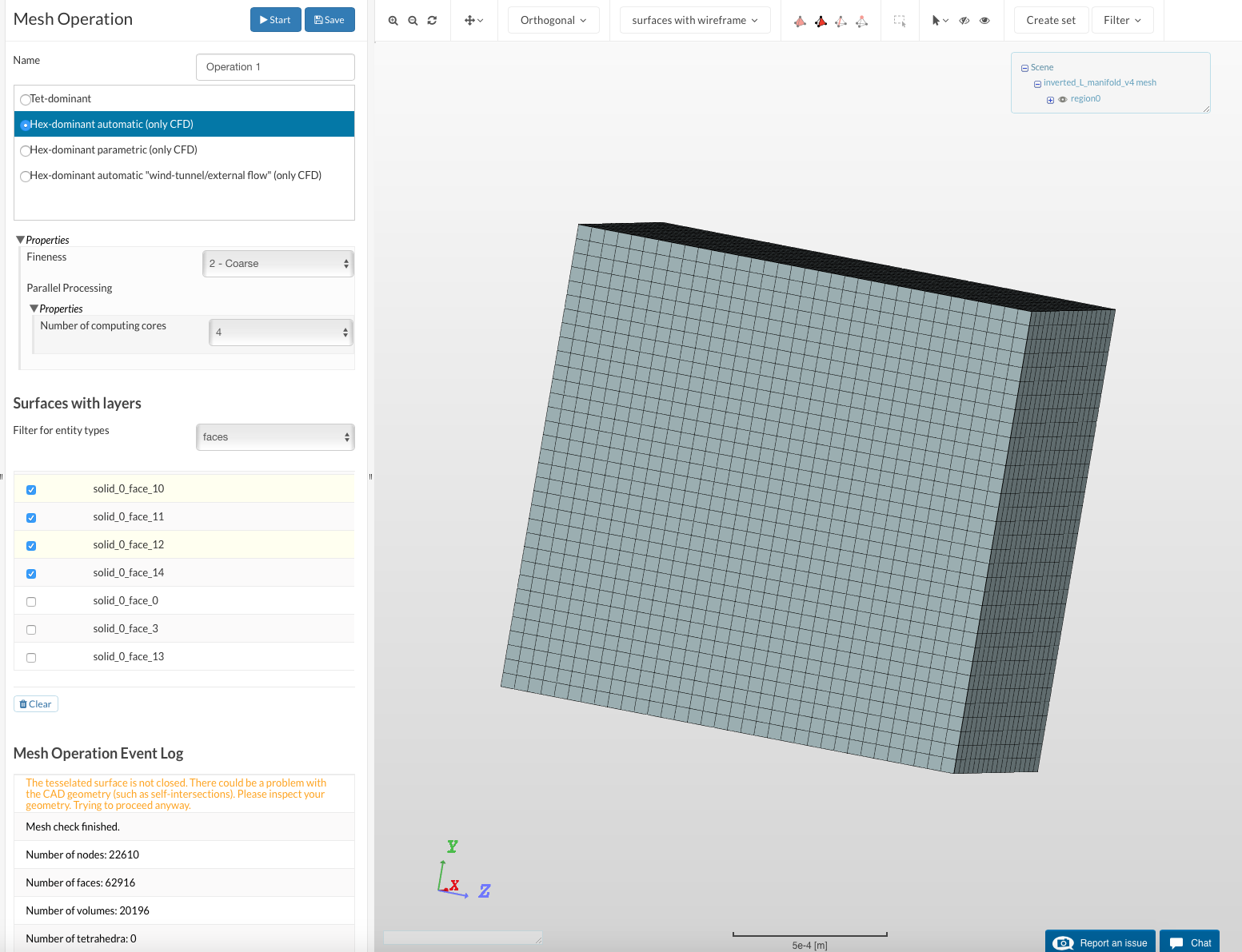
When creating meshes, my most recent attempts have resulted in the warning message “The tesselated surface is not closed. There could be a problem with the CAD geometry (such as self-intersections). Please inspect your geometry. Trying to proceed anyway.” and the creation of a boundary box without a mesh inside.
After trying to solve this with various methods (changing mesh parameters, changing CAD file (STEP format), modifying design), I was unsuccessful. Further testing reveals that even trying to create a new mesh in a project with an already-fine mesh with the exact same parameters fails in this way. Any help would be appreciated.
Already had a look at your case which requires a bit more investigation. I am currently looking into it and I will get back to you with more details asap. That might take some time but I won’t forget you, no worries
I have used the parametric mesh option in order to get a proper mesh which is probably the best option in this case. You can have a look at it by going to the mesh tab and clicking on Optimized Mesh.
Unfortunately, such a fine mesh is unsuited for what I am trying to do. I am simulating multi-phase flow through this component (which is designed to have inefficient flow), so my simulations are pretty computation-intensive. A coarser mesh is necessary for me to keep my core hour usage and simulation time from skyrocketing.
Would it be possible to make a coarser mesh? I noted that despite the parametric mesh option, it still threw the warning of “The tessellated surface is not closed” despite having a correctly-shaped mesh.
Thanks, creating parametric meshes seems to solve the problem. As a side note, I have been consistently stopped when simulating by unknown causes that force the simulation to go down to an insanely small timestep and subsequently error out or run out of time without getting any farther. The stop rarely comes at the same exact time twice, and can occur at any percent done through the simulation (though it tends to come around 1-2% in).
Some of the changes you made are definitely improvements over what I was working with. I can’t use the end result, however. The simulation did not produce enough frames (did not write enough timesteps?) to observe the flow, the end goal of my efforts. The contour filter is necessary to see the difference between air and water, but the filter does not provide useful results unless it is present from frame 0, tracking the largest surfaces of water. I suspect this is due to splashing, etc. Also, from what I could see, the initial conditions of the phase fraction were changed from all air to all water, which invalidates the simulation.
Looking at the simulation run event log, the “the Courant number (CFL) exceeded the limit of 1” warning appeared in your run as well, in much the same way as it has been appearing for me. However, for your run, the computer did not automatically reduce the timestep as it did with mine after implementing what seemed to work of your changes.
“deltaT = 9.04455561736e-18
Time = 0.02919830365346554
deltaT = 8.93966762496e-18
Time = 0.02919830365346555
deltaT = 8.83621746158e-18
–> FOAM Warning :
From function Time::operator++()
in file db/Time/Time.C at line 1055
Increased the timePrecision from 12 to 13 to distinguish between timeNames at time 0.0291983036535
Time = 0.02919830365347”
Incredibly small timesteps like these are, I think, what are slowing the simulation down.
I appreciate the help with this frustrating problem. Thanks again for assisting me with it.
I was wondering if you have managed to make sense of the problem. After more tweaking, I have managed to somewhat consistently get the simulation to .2-.25 seconds. Around there, at a varying time, it either goes to an insanely small timestep (e-111 s scale in one case!) or errors due to numerical instability.
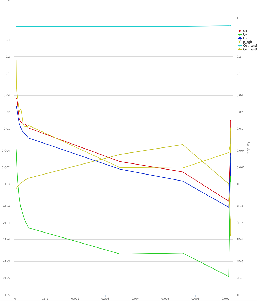
The best that I can figure is that the solvers (maybe GAMG?) are having problems solving for Uz or p_rgh based on where the error occurs:
ExecutionTime = 6956.2 s ClockTime = 9150 s
Courant Number mean: 0.0142883343508 max: 0.499998790772
Interface Courant Number mean: 0.00468809644726 max: 0.433567965043
deltaT = 9.75108642052e-06
Time = 0.245343919743
MULES: Solving for alpha.phase1
Phase-1 volume fraction = 0.369618257895 Min(alpha1) = 0 Max(alpha1) = 1.00000027578
smoothSolver: Solving for Ux, Initial residual = 0.000469376659999, Final residual = 2.97455555912e-06, No Iterations 1
smoothSolver: Solving for Uy, Initial residual = 0.000258956071055, Final residual = 1.64353431208e-06, No Iterations 1
smoothSolver: Solving for Uz, Initial residual = 0.000395826820054, Final residual = 2.46009678776e-06, No Iterations 1
[8] Signal 8 encountered
[8] Going to reraise SIGTERM after writting
[8] Resetting old handlers (just in case)
[8] Unset SIGFPE(8) signal handler
[8] Unset SIGSEGV(11) signal handler
[8] Unset SIGQUIT(3) signal handler
[8] Writing old times:
[8] 1 times to write
[8] Write t=0.245334168657 to “processor8/0.245334168657”
[8] Writing current time 0.245343919743
[8] Printstack:
[8]
[8] #0 Foam::error::printStack(Foam::Ostream&) at ??:?
[8] #1 Foam::writeOldTimesOnSignalFunctionObject::sigHandler(int) at ??:?
[8] #2 in "
[8] #3 Foam::GAMGSolver::scale(Foam::Field&, Foam::Field&, Foam::lduMatrix const&, Foam::FieldField const&, Foam::UPtrList const&, Foam::Field const&, unsigned char) const at ??:?
[8] #4 Foam::GAMGSolver::Vcycle(Foam::PtrList const&, Foam::Field&, Foam::Field const&, Foam::Field&, Foam::Field&, Foam::Field&, Foam::Field&, Foam::Field&, Foam::PtrList >&, Foam::PtrList >&, unsigned char) const at ??:?
[8] #5 Foam::GAMGSolver::solve(Foam::Field&, Foam::Field const&, unsigned char) const at ??:?
[8] #6 Foam::fvMatrix::solveSegregated(Foam::dictionary const&) at ??:?
[8] #7 Foam::fvMatrix::solve(Foam::dictionary const&) at ??:?
[8] #8
[8] at ??:?
[8] #9 __libc_start_main in "
[8] #10
[8] at ??:?
When we check the saved states we see that the results were stable until some point (at least 150 steps).
This diverges near the outlet. Could be due to “splashing effect”. The velocity seems to be a bit too high though. Did you make a simple theoretical calc before doing this?
Could you calculate the time taken for the fluid at inlet to reach the outlet? Considering your dimensions and velocity of flow I believe this is going to be very high. As a first step I would consider defining a smaller velocity.
The correct run is labeled “26”, and the saved state maps to the settings I use. At around .33 s the flow through the component smooths out a lot. If only I’d been able to make the earlier runs simulate .05 s longer!