Mesh Could Not Be Generated ERROR - increasing mesh fineness

Hello

I am having a problem with my mesh failing with the advice to “Increasing the mesh fineness or adding local refinements to geometrical details potentially fixes this issue.” I have already searched the forum to help find an answer, and while i know i can just increase the surface refinement level, I am trying to avoid that. I have tried to optimize my meshing strategy so that i can run a half car simulation using 32 cores and have an end result under 10-11 million total cells. This will allow me to also complete full car simulations, hopefully without memory issues.

I am confused as to why this mesh failed because a few weeks ago i ran a successful DRS mesh with:

  • The same exact geometry (minus wing angle changes without DRS)
  • The same exact surface,region, and feature refinements (I copied the DRS mesh)
  • The same exact mesh quality settings - bounding box - etc…

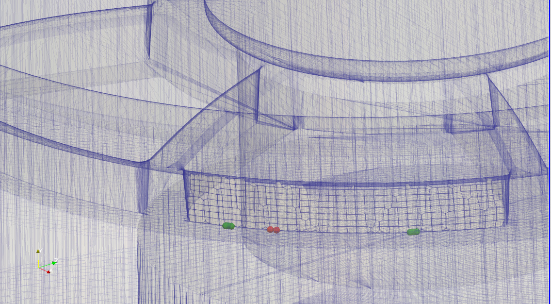
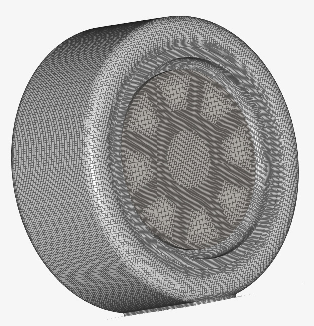
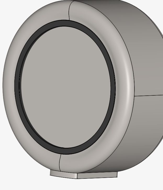
Here is my first successful DRS Run

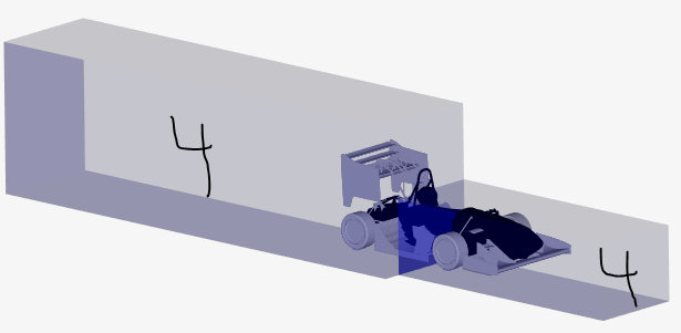
The only difference was that i split my wake region region refinements into two sections with a lower level farther away from the car to help reduce the total cell count even more.

DRS run with only level 4 region refinement
image
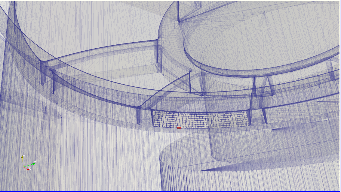
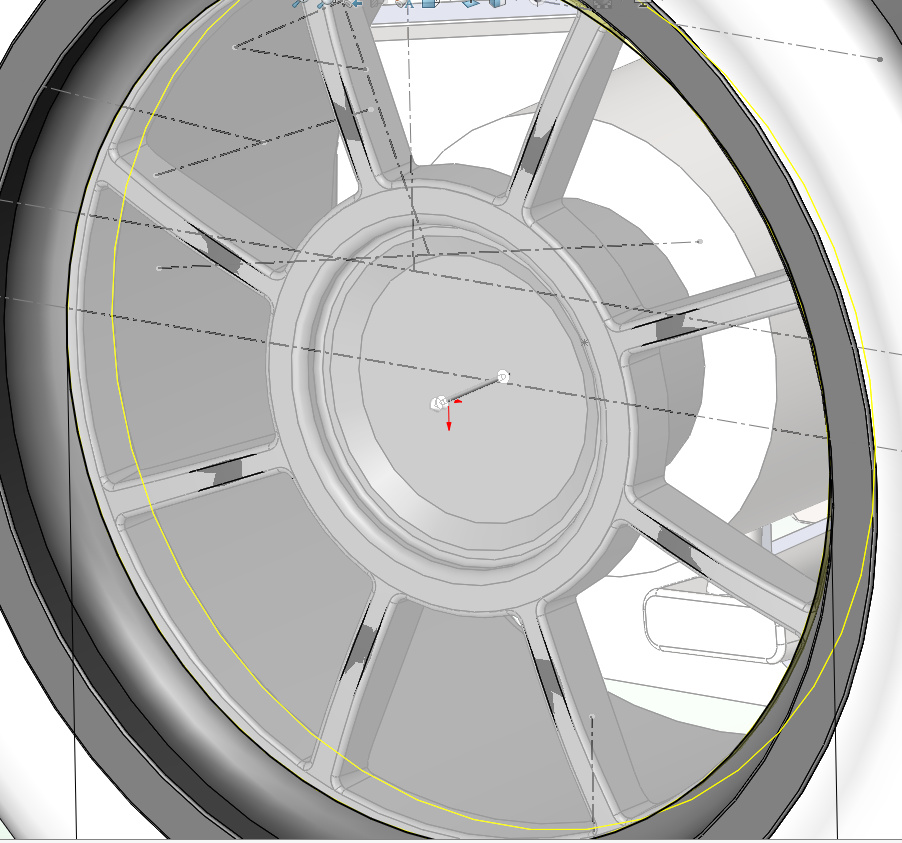
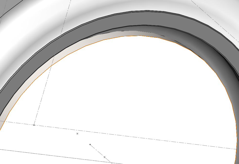
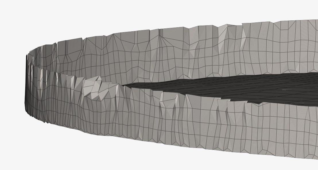
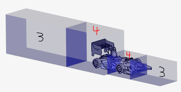
And here is the Failed mesh run shown below

Split region refinement to levels 3 & 4
image

I found a previous failed mesh thread of mine actually that if the mesh achieves the “finalizing parallel run”, which my mesh attempts did achieve, that the mesh was actually successful but was unable to save.

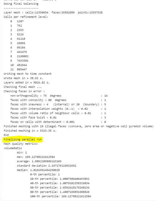
This is from @Get_Barried in my old thread post Here

It mentions “Finalising parallel run” which means your mesh, as mentioned, is actually successful. However, for some reason it was unable to save. So this does point to issue Two where you’ve actually run out of memory for whatever reason. Your mesh was only 16 million cells which is quite a bit but not too drastic. Try deleting all your unused meshes/projects/geometries/simulations and see if you’re able to mesh then.

Anyone know a possible fix without increasing the total cell count?

Thanks (again) for your very detailed description of your problem! :slight_smile:

Might be a very interesting topic for our mesh engineers to take a look at, will forward this and we’ll keep you posted!

Also tagging @yosukegb4 as well as @Get_Barried here to maybe identify other issues like CAD related problems which might cause this.

Cheers and stay safe!

Jousef

Hi @dschroeder,

first kudos to your model, looks really exciting and speedy, even though they guy should wear a helmet based on that.

I looked into the problem of the mesh. What happened here is that there are tiny degenerated cells that share faces with more than one neighbor and make the mesh invalid.

In your case it is just one cell located at the rear tire.


I found that there is a tiny little gap between the MRF zone and the wheel.

I pulled it a bit further to exactly match and re-run the mesh in hope of this small adjustment fixing the issue. Spoiler alert it didn’t, I got the same issue at close spots:

It explains the late reply though as - while investigating and changing the CAD/setup doesn’t take much time - it takes quite long to run the mesh and see if it works. I’ll try if I can reproduce this problem on the wheel only, then it should be easier to see how to fix it.

What we can do to improve the situation is exposing the problematic face and position of the issue of course. This problem doesn’t happen too often, so we didn’t do this so far as we are mainly investing on the Standard mesher where similar errors are already exposed in the Event Log.

I’ll update if I can make it work. As mentioned just takes time to run, so I thought I share the insights, maybe you also want to try something based on it.

Best Alex

4 Likes

Wow thanks for such a large time investment and detailed response!!!

I did have to redo some of the mates for the wheels so maybe i did cause this problem myself haha. Its crazy how such minor imperfections can cause a failure, but i guess thats just a part of simulating.

i understand that having CAD files water tight is important but there are so many faces to this model that it is difficult to troubleshoot problems like this. I wish there was a “pre-meshing” program that could find potential problems like this. Something like that might already exist i just dont know about it.

Also, how are you able to tell that this one bad cell caused the problem? As in - are you using a program similar to what i described, that can find cell intersection conflicts like in the pictures you shared?

Anyways, I can also run some wheel only tests in parallel to see if i can find the problem as well.

Thanks a lot!

Dan

I have sucessfully meshed the wheel with MRF cell zone. Since this worked no problem, i will try the full car model again.

1 Like

So i did another full run with my MRF zone having a new mate, Using the same wheel assembly that worked above. The Latest Run failed again with the same probelm. I have checked my DRS run multiple times for and differences in the surface or region refinements but found nothing. I have not made drastic changes to the Geometry, only changing ride height and pitch angle, and of course element angles. I have also successfully meshed this entire car in run 2.1 with normal element angles, just without my radiator fan setup.

Edit I also just checked the mesh log and i only have 37 illegal cells.

Why is my mesh continually failing? I assume, as you have suggested, that it most likely has to do with the CAD file. The only thing i can think of is to continue checking individual parts until i find the problem. There must be a better way, and ideas?

team account so i can post again :slight_smile:

New tests to make this thing work. For some reason the single front tire assembly meshed just fine as shown above. So i tried both front an rear wheels only, and the problem came back.

Since this mesh failed, I thought I would try changing the MRF CAD model slightly to see if it would help fix the problem. First I increased the diameter of the MRF geometry from the exact size of the wheel (previously -289mm) to 290mm and also thickened the front face. I thought the front face could be the problem because it is only 4mm way from intersecting the spokes as shown below.

MRF face reduced 4mm to show interference point

Here is the extended MRF zone so that cells cannot snap to the wheel spokes

Upon looking at the single wheel mesh that was successful, I noticed the MRF zone edges do not look too good. Here is a pics of the bad faces in the MRF zone

The larger sized MRF test ended in failure as well. After this, I attempted to increase the Cell level to 8-9 min max, however this also resulted in mesh failure.

Then i changed the model again so the MRF zone is far away form the wheel edge shown below, also failed

I really dont know what the problem could be. Is it really a problem with the MRF zone? The only advice I have seen for MRF CAD best practices is to have the MRF model exactly touching the edge (how i had the MRF zone the whole time) or far away (as i just tried to mesh but failed)

EDIT
I just added another MRF geometry shown below. It completely encloses the spokes and edge of the wheel. - Also failed

1 Like

I was able to get the wheel geometry to mesh correctly. The problem was, i believe, due to the small radius at the edge of the wheel connecting poorly with the MRF zone. I have since simplified the wheel design and taken out most of the small curvatures because the HEX mesh seems to like sharp edges better.

Now there is a new problems. I receive the following error and the output from the meshing log
image

Merging 24058 duplicated points …

Edge intersection testing:

Number of edges : 36044265

Number of edges to retest : 0

Number of intersected edges : 3542256

Merged points in = 3840.66 s

Converting baffles back into zoned faces …


[[22179,1],2]: A high-performance Open MPI point-to-point messaging module

was unable to find any relevant network interfaces:

Module: OpenFabrics (openib)

Host: f354a6272343

Another transport will be used instead, although this may result in

lower performance.


[f354a6272343:00159] 31 more processes have sent help message help-mpi-btl-base.txt / btl:no-nics

[f354a6272343:00159] Set MCA parameter “orte_base_help_aggregate” to 0 to see all help / error messages

[0]

[0]

[0] –> FOAM FATAL ERROR:

[0] One of two duplicate faces already marked as duplicate.

This means that three or more faces share the same points and this is illegal.

Face:1161925 with local points:4(7667 7667 62853 7765) which are in same order as face:1167376 with local points:4(7667 7765 62853 7667)

[0]

[0] From function static Foam::labelList Foam::localPointRegion::findDuplicateFaces(const Foam::primitiveMesh&, const labelList&)

[0] in file regionSplit/localPointRegion.C at line 594.

[0]

FOAM parallel run aborting

[0]

[0] #0 Foam::error::printStack(Foam::Ostream&) at ??:?

[0] #1 Foam::error::abort() at ??:?

[0] #2 Foam::localPointRegion::findDuplicateFaces(Foam::primitiveMesh const&, Foam::List<int> const&) at ??:?

[0] #3 Foam::localPointRegion::findDuplicateFacePairs(Foam::polyMesh const&) at ??:?

[0] #4 Foam::meshRefinement::mergeZoneBaffles(bool, bool) at ??:?

[0] #5 Foam::snappyLayerDriver::addLayers(Foam::layerParameters const&, Foam::dictionary const&, Foam::List<int> const&, int, Foam::decompositionMethod&, Foam::fvMeshDistribute&) at ??:?

[0] #6 Foam::snappyLayerDriver::doLayers(Foam::dictionary const&, Foam::dictionary const&, Foam::layerParameters const&, bool, bool, Foam::decompositionMethod&, Foam::fvMeshDistribute&) at ??:?

[0] #7 ? at ??:?

[0] #8 __libc_start_main in "

[0] #9 ? at ??:?


MPI_ABORT was invoked on rank 0 in communicator MPI_COMM_WORLD

with errorcode 1.

NOTE: invoking MPI_ABORT causes Open MPI to kill all MPI processes.

You may or may not see output from other processes, depending on

exactly when Open MPI kills them.


mpirun has exited due to process rank 0 with PID 160 on

node f354a6272343 exiting improperly. There are two reasons this could occur:

  1. this process did not call “init” before exiting, but others in

the job did. This can cause a job to hang indefinitely while it waits

for all processes to call “init”. By rule, if one process calls “init”,

then ALL processes must call “init” prior to termination.

  1. this process called “init”, but exited without calling “finalize”.

By rule, all processes that call “init” MUST call “finalize” prior to

exiting or it will be considered an “abnormal termination”

This may have caused other processes in the application to be

terminated by signals sent by mpirun (as reported here).

It seems that the problem lies in three faces sharing the same point which is illegal. Is this due to changes in ma CAD geometry or with the snapping iteration?

I was finally able to get a working mesh. The suspension geometry had some very small intersections that i think caused the problems.

1 Like

Team account for another post

So this problem has come back for me. THE MESHING FAILURE IS GETTING FRUSTRATING!

I have recently done a lot of testing to mesh settings and changed CAD geometry to reduce non-orthogonality in my half car mesh. This was done through meshing assemblies on the car separately, making any changes and improvements as necessary.

  • Wheel assembly - Tire, wheel, motor, MRF zone, contact patch

  • Suspension Components - A-Arms, Suspension, ball sockets for A-Arms

  • Mono - Mono, Main hoop, head rest

  • Radiator Assembly - Porous media, rad mount, rad exhaust, Rad tubes, Rad fan, Fan housing, Fan MRF zone

Test Meshes

I tested these groups, mostly with success in geometry changes to reduce the non-orthogonality. However, when everything is added together, i get the same error - mesh fineness should be increased. Every mesh makes it to the "finalizing parallel runs" stage.

Full Car Attempts

ALL of the testing i have done so far is only to get a better mesh for the half car and get stable settings. I still need to make full car meshes, with models at different ride heights, roll, steering angle, and yaw angle. This means i could have this problem repeated when i move to the full car simulations.

DOES ANYONE know what the MAIN cause is with this error? Do i really need to have the mesh finer? From the successful meshes i have already done on the half car, I fell that the geometry is adequately represented.

Am i missing something?

Hi @dschroeder
first of all sorry for the trouble you’re encountering.

I checked two of the meshes: RH.33.65_Y.0_R.0_P.-0.015_SA.0_S.10__5 and RH.33.65_Y.0_R.0_P.-0.015_SA.0_S.10__4

The error for this mesh is that there are 1 or 2 mesh faces which have 3 adjacent cells each. This is a bug in snappyHexMesh which leads to a broken mesh and whenever this happens, we detect the situation.

I can give you the coordinates of those faces:
[7.775154e-01, 4.500926e-01, 3.899010e-01], [7.788766e-01, 4.502958e-01, 3.896274e-01], [7.780269e-01, 4.501904e-01, 3.897789e-01]
and
[2.560420e-01, 1.234988e-01, 8.368089e-01], [2.565703e-01, 1.235060e-01, 8.370202e-01], [2.569119e-01, 1.234975e-01, 8.373970e-01]

Mesh “5” has both of these broken faces, number “4” has only the second one.

Usually it helps to nudge the mesh a bit in those places, either by making it finer, or coarser.

Is this information useful to you?
Johannes

1 Like

@jprobst YES this is very helpful!

I have been trying everything and was wondering if I was causing the problem. I will check these points if i can, Im not sure how to in simscale but maybe i can check the geometry in solidworks. Ill post anything i find but its a bit
troublesome that the mesh wont work at all just because its “off” a bit.

Is there any way to check things like this before i mesh. Otherwise im flying blind the whole time trying to figure out the problem. Is this a feature in paraview or some advanced OpenFOAM wizardry?

EDIT

So i found the two points

One is by the pushrod. I had just changed this ball socket end from square to round because i saw some Non-orthogonal cells in this area

The second is in the Rear wing holder, where i havent made any changes to this geometry at any point
**

**

I think checking the geometry is a great idea to start with. Most likely there is going to be something in the vicinity of those points (e.g. a sharp edge, or a tight gap).
Unfortunately there is no way to predict that this issue is going to happen. It’s something which can only be seen after meshing (when it’s too late).

So i just edited the post with the points as you have probably seen.

I had done not only Mesh setting research but also read through the CFD Online forums and have concluded that my search for Non-Orthogonality reduction is a bit foolhardy. The ONLY way to have really good cells with low Non-otho would be if i simulated a box haha.

This basically means that i cannot avoid bad cells, only try to reduce them in important areas. Also with what i am doing I need to change the position of the model, which could either cause more problems such as this one, or solve them altogether. Too bad theres no Pre-Mesh geometry checker, or at least an output in the meshing log that says exactly where the adjacent cells are located… (in the red ERROR box)

So how were you able to tell where they were? It would be extremely useful to know how to find point such as this. Im assuming it was from the meshing log?

Edit

Looking more closely this point is actually on the backside of the holder

Great, I think you’re on the right track with this investigation.

I was able to find the error in our database. There we have more information available than we can show in the UI. We’ll consider making the location of those meshing problems more visible to the user. I agree that it would be useful to know where exactly the problem is located.

Hey @jprobst

Could you look at another mesh for me please? Its the same problem with three adjacent cells. This one is the first of three skidpad runs i will be doing. This means that the vehicle setup will stay constant, only the front/rear wing locations & Angle of attack will change. Hopefully you can detect where the problem is and i can make a quick fix.

Thanks!!

Hi @dschroeder
no problem. The location is
[1.090938e+00, 3.494176e-01, 1.982500e-01], [1.091238e+00, 3.495908e-01, 1.982380e-01], [1.089934e+00, 3.489482e-01, 1.982449e-01]
Hope that helps
Johannes

1 Like

Johannes,

Thanks so much for checking that for me. I am re-running the mesh now along with the two other skid pad vehicle setups. I hope that the different yaw angles of the other setups cause less problems, but unfortunately as you said i can only see if there is a problem after the mesh fails. I wish there was a way to foresee this to avoid the waste in core hours. Anyways, ill let you know if the other meshes have the same issue

Dan

1 Like