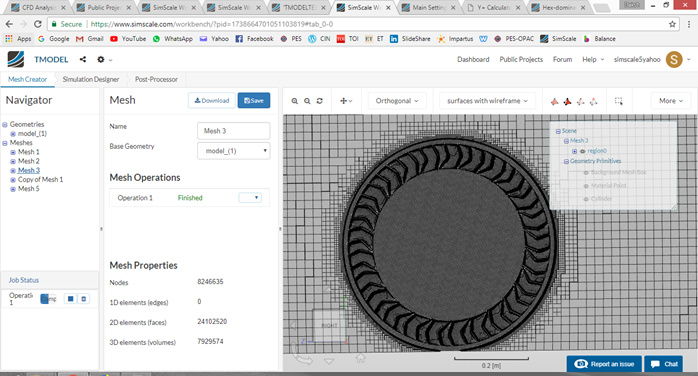
I generated such an image with mesh clip but now when i do the same just the solid body comes in gray colour and not these wireframe. Please can you enumerate the steps to get a slice in between to see how the mesh is around my body ?
@jousefm Can you help out please ?
1 Like
Hi @simscale5yahoo!
Can you tell me what you mean with “grey colour”? If you mean the geometry itself, there is no way to apply a mesh clip filter to it as this is only possible for meshes as the name indicates.
Maybe I did not get your question. Please post a picture of the issue if I didn’t get your point.
Cheers and thanks!
Jousef
Hey @jousefm !
How have you been sir ? ![]()
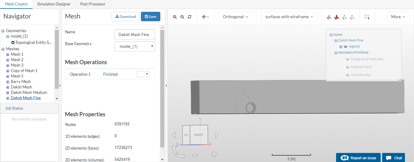
When i apply the mesh clip filter such an image is coming whereas i want to see how the meshing has happened with teh rest of the surroundings like the EARLIER picture i posted. How can i get that can you please tell ?
Hi @simscale5yahoo!
Seems to be an issue that I have to discuss with my colleagues. I will get back to you as soon as I know more 
All the best!
Jousef
Thankyou because i need to showcase such a mesh clip to my fellow members to have a better understanding of the meshing
Seems like issue at simscale side only because i am applying the same steps with which i earlier got that section image of the mesh. Please lemme know as its gets resolved
Thanks alot! Any more help i require will bug you again ! 
1 Like
Hey @jousefm i tried to apply the mesh clip again to see how the mesh is happening around the tyre (body) but again the same grey colored region is coming. Has the issue been resolved at simscale end ? Any updates when can i see a meshed region like the first pic i posted in this thread ?
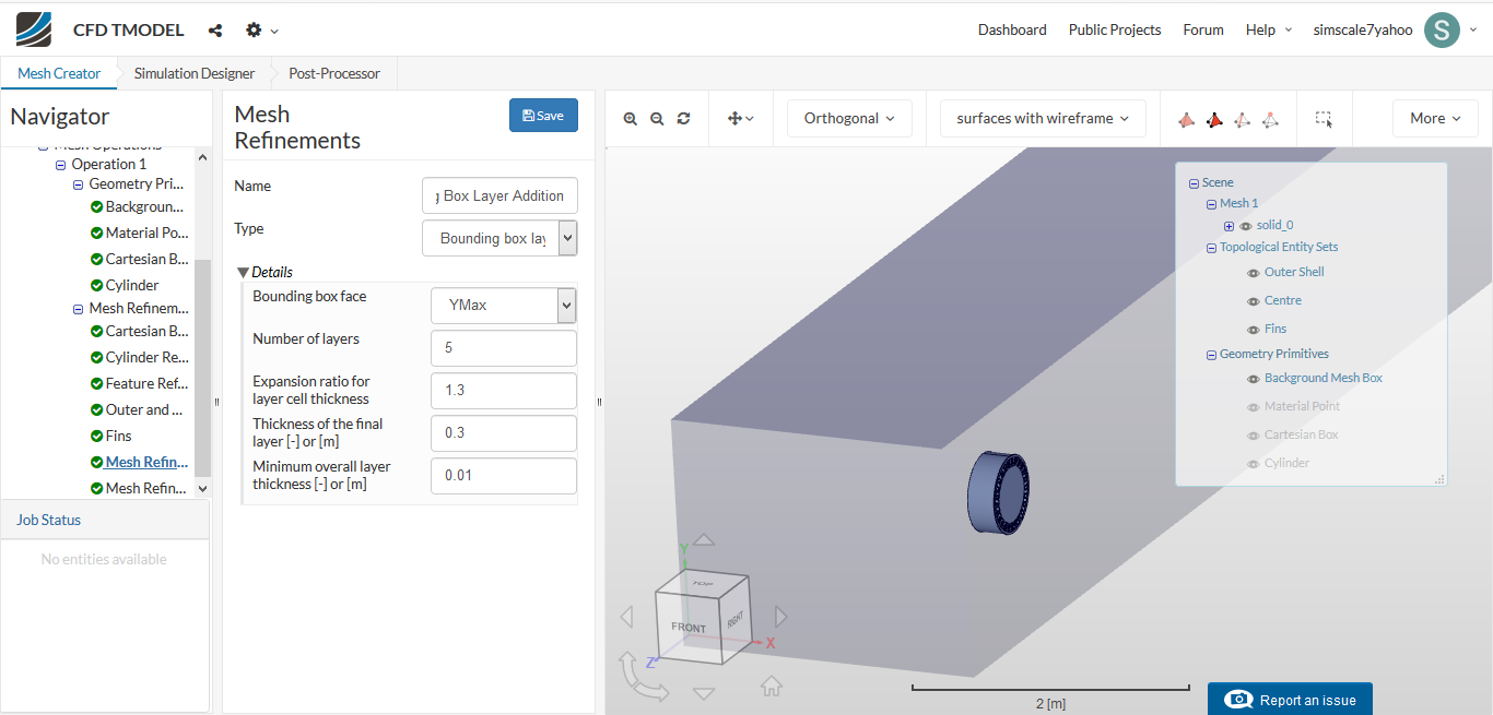
Also i wanted to know for this case for bounding box layer addition will my bounding box face be YMIN OR YMAX i am confused with that. basically i want the bottom wall ( road) to have bounary layer to study the effects where the road touches the wheel.
@jousefm if you can please help out ![]()
Sorry for getting back to you so late @simscale5yahoo!
I will ask if there are any updates For your second question you would have to choose YMin as your floor is located at the minimum y value! Hope that helps - getting back to you asap.
All the best!
Jousef
Thankyou so Much
Also @jousefm or @1318980 i know the first cell layer thickness for my case for a y plus of 1, that is 0.000025 metre.
Now what all inputs should i give in the details column to get a proper boundary layer around my body as well as ground? Can you suggest please ?
My another doubt is that i apply inlet velocity of -14 m/s in z direction, and for ROTATING case of wheel i apply moving ground wall of -14m/s at z but i am not sure whether for rotating wall velocity have to apply 47.14 rad/s or -47.14 rad/s. Basically i saw some right hand thumb rule for rotation of tyre but in that video they didnt exxplain properly how to apply it . So for my case when the ground is moving - 14m/s in z direction should the tyre have + or - 47.14 rad/s rotational velocity ?
Hi @simscale5yahoo,
For the body, you will have to calculate this yourself based on the y+ you calculated. I would recommend for a start of using a wall function and having your y+ to be anywhere between 30 and 200. We’ll get to actually selecting the wall function later but do recalculate your y+ to as mentioned.
On calculating the values to input into the “Inflate Boundary Layer” (Note it is not the same as Bounding Box Layer addition) lets assume we maintain an expansion ratio of 1.3 (which is default) you will then need to open up Microsoft Excel (for ease of calculating out the layers) and set your calculated first layer (Delta S if you are using the Pointwise Calculator) multiplied by the expansion ratio which remains constant for every increment of the layer. Once you’ve done that you can calculate up to as many layers as you like, but for now lets set it to 5 layers so you should have 5 sets of values with the calculated first layer as the first value. Then you can sum the layers up to obtain the overall layer size.
Once you have all the data above, you can input your “thickness of the final layer” as the final layer size in your data sheet (layer 5) and the sum of the overall layers as the “minimum overall layer thickness”. Just make sure that sum is slightly smaller than the actual sum because of decimal places, you dont want your layers to just disappear. (Example if your sum of layers is 0.51m then input it as 0.5m to be safe). This should settle your boundary layer inflation.
For the inlet and subsequently the ground, this is slightly more grey as to be accurate you have to refer to literature that explicitly states what the minimum inlet cell size near the ground should be. However for a start just leave the values of your “Bounding Box Layer Inflation” to default values and we’ll worry about accuracy later. More important at this point to achieve the inflation layer to allow ground effects to be present first.
So this is a little difficult to characterize as it is based on what you specified as the rotation axis of the wheel and its direction. For this case its either +ve or -ve X. For say -ve X, you will be looking at your wheel from “outside” to the origin and as such for the wheel to move forward, you should expect your rotation to be clockwise. Vice versa for the other defined rotation axis. I would assume that the rotation speed follows the clockwise convention like in this sample case so a positive value of 47.14 rad/s for a Y of -1.
Hope this helps. Do refer to the sample project as it is well made and applies very well to your case.
Cheers.
Regards,
Barry
2 Likes
Thanks for jumping in Barry!
Cheers!
Jousef
1 Like
@simscale5yahoo Same problem is happening with me also. Mesh clip filter is not applying. Have you found any solution to the problem ? @jousefm
Hi @Fozan,
Do your post your project link as mentioned.
However, regarding the mesh clip you should note that if the mesh has a lot of nodes the mesh clip may not work. A good way to check your mesh then would be to simulate it for a very short time step like 0.01s just to get 1 data set out and open it in paraview where you can select “surfaces with edges” and observe the mesh at any point.
Cheers.
Regards,
Barry
Hi @Fozan & @simscale5yahoo!
The issue has been resolved, please confirm if everything works as expected!
Best,
Jousef