Hello,
i´m currently working on a water flow simulation in water tank. Everytime I try to start the simulation I get the “Maximum number of iterations exceeded” error.
everything seem normal for the boundary and also the meshing.
PowerUser Darren (@1318980) and I had a look at the project and it seems that it keeps failing for some reasons we still have to figure out. We try to make this work and get back to you as soon as we know more!
thank you very much sir for your reply…if you get anything about my problem here and want to correct something about the simulation…please do so because i am new to this simulation and in the process of learning
i am new to Simscale and my project is about water flow in and out from the water tank with diferent temperature.
in this case i want to do the CHT simulation of the solid body when the water flow with different temperature and pressure,
but there are some problems with my geometry in this project.
The meshing seem not right.
It is the problem happened because of my CAD model?
I had a look at the other simulation you have set up but still need more time to figure out what is going on. There seems to be a problem with the temperature causing the enthalpy to do uncommon things. You neither have negative density or something like that. Might take a bit. Hope that is fine though and you are not so much under pressure
Thank you sir @jousefm !
i also did another simulation but this time i turned on the ´´Boussinesq approximation´´…so far there is no error,
i will inform you if the simulation finish properly or not.
i also have some question regarding the overlapping geometry, actually how to avoid that overlapping surface?
the geometry have two small solids geometry inside it, a fluid geometry, and also the outer solids.
for this project…i want to do the CHT simulation and wanted to know the temperature distribution inside the solid when the water flow with temperature.
and among other things, the simulation Run 2 under ´´convective heat transfer 1´´ in my project, the simulation ran smoothly but the results is little bit weird for me.
my start time is 0 and my end time is 3040, i thought by the end of the time within 3040 s,the water temperature in the tank will completely 519.25 K, but just half of the water temperature reached more than initial temperature,could you explain to me about this and what action do i need to take?
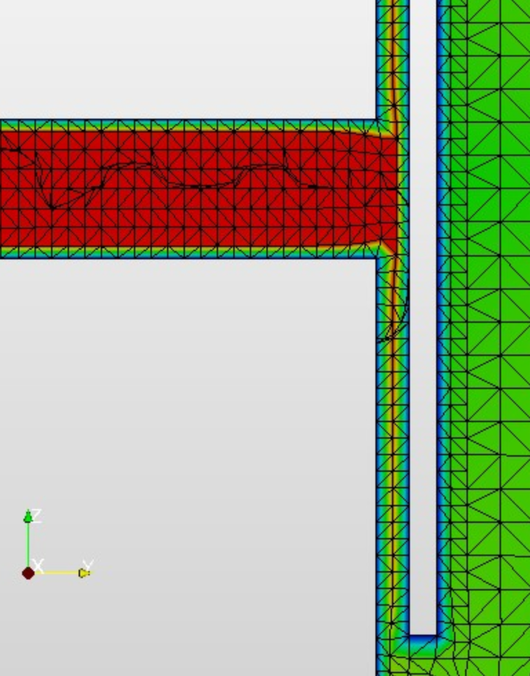
2 cells in the thin channel aren’t fine enough, you could just inflate boundary layer cells here.
reduce under relaxation values in the numerics, this reduces instability but makes convergence take longer.
Set the initial temperature in initial conditions to be the inlet temperature, if you expect 519.25k there is no need to make the solver do extra work.
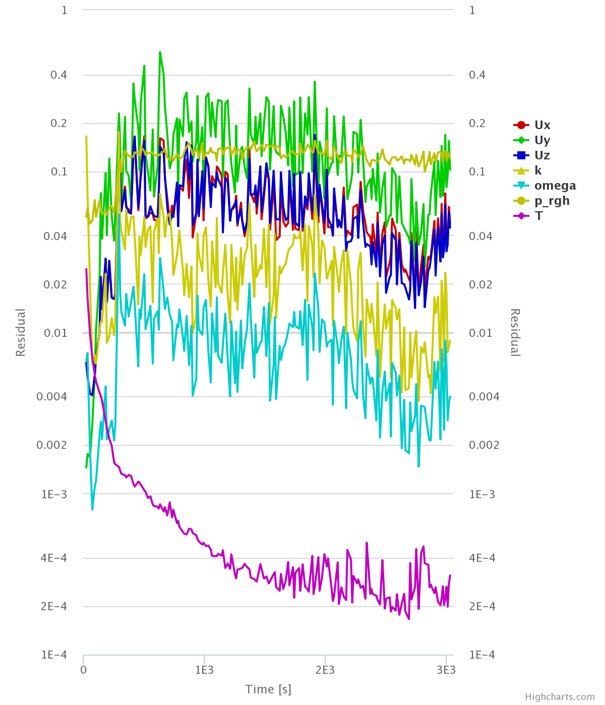
add a result control like area averages to the two little plates and monitor their convergence for velocity and temperature, this gives us a good insight as to what is happening within the solution whilst it is still solving
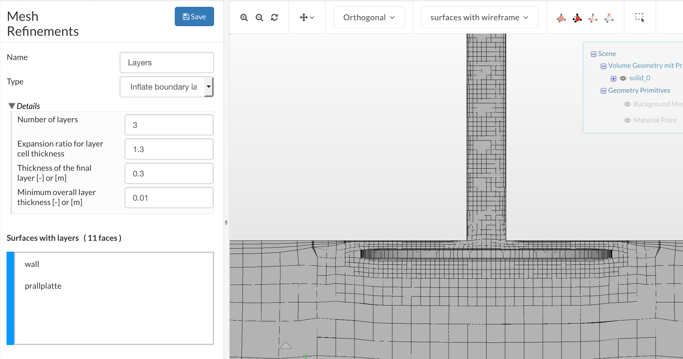
Sure, the surfaces that need layers are really all surfaces where the no-slip condition is applied. In your case, this would be every surface except the inlet and outlet. Here is the setup I used to quickly illustrate this:
Hello Sir @1318980 ,
I already did the meshing process of inflate boundary layer under the name “Part studio 4 mesh” but it said error to my meshing…
could you help me about the problem?
Not entirely sure why the error was produced, I suspect something to do with the refinement level or selection itself, however, I have produced a mesh that is of good quality and will deal with your thin channels well:
i already made a copy from your meshing of my project and also did the simulation, so far the simulation ran smoothly thanks to you.
Here i paste my link of the simulation project
Could you check the simulation “Run 1” for me please…
i actually thought that after 3040 s, all of the tank will be full with the temperature of 519.25 K,but it is only half of the tank…
could you please help me with this?..is that the mass flow rate is too small?
and also how do i get after 3040 s,all the water temperature in the tank get average of 519 K?
Hello @1318980@jousefm,
Thank you very much Darren for your help.
Maybe i need to explain more detail about the project so you guys can further assist me.
Firstly the water tank already filled with water
at 0 s themperature is 416 K, there is no water flow or whatever.
and then the water tank storage will be begin to fill with water that have about…mass flow rate with 0.2753 m/s and with T=519.25 K and with P=49 bar
and after 3040 s,all the water in the storage will completely become 519.25 K.
so i want to run the simulation and see what happen when for example at 500 s,maybe just half the water will warm and after completely about 3040 s,the water inside the tank storage will be completely get 519.25 K.
So i need the advice from you guys about this project…
i already did the simulation according to the advice from sir Darren and it still in computing.
if someone can help or give some advice about how to properly do the simulation…please do so…
Ok, so for this you need a transient simulation. What you have been solving was a steady state simulation, this is time independent and therefore, the end result is the result of many iterations. In a steady state you cannot think of the time steps as actual time but more like how many time steps it has run.
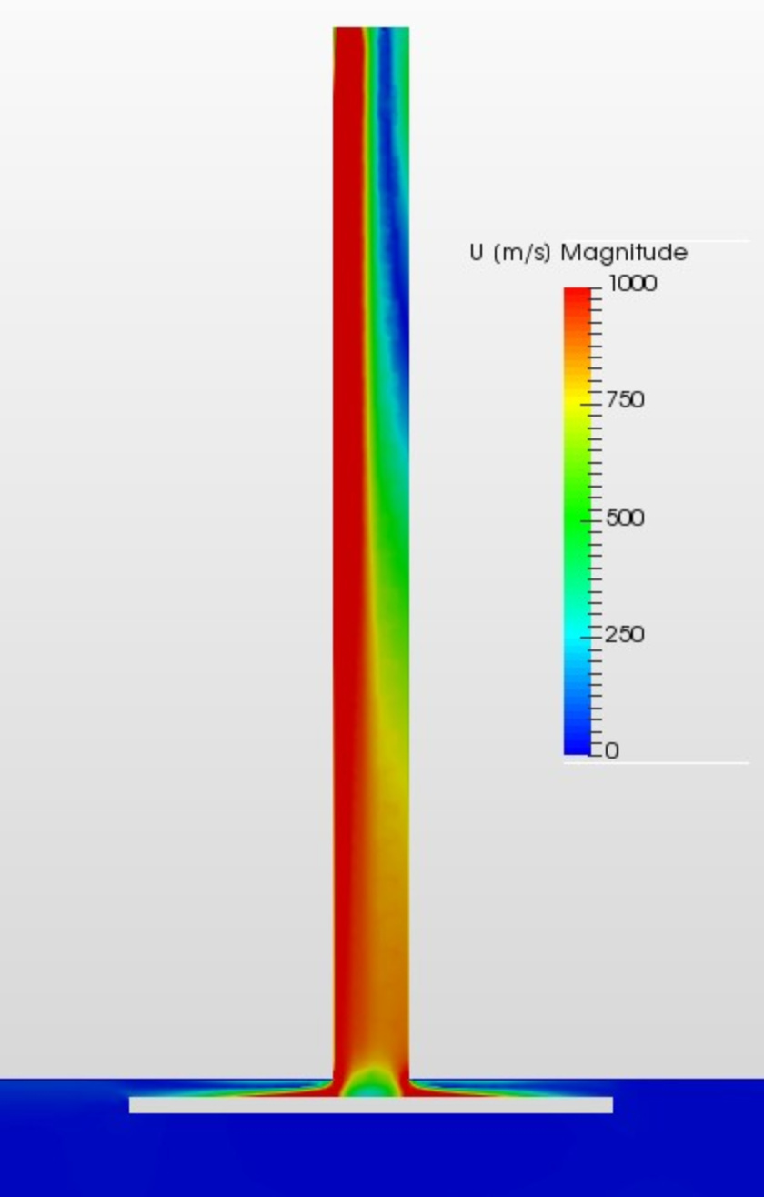
A transient solution with velocity this high at the inlet might be very computationally expensive.
Thank you very much sir for your help! .
I already did the transient simulation under “convective heat transfer 2” “Run 2”…
and also have calculated my water flow velocity with 0.0696 m/s…
I did the simulation with this velocity value at inlet within 3040 s and still didnt get the results that i expect.
Would you check for me please the simulation that i ran and correct me if i have done something wrong with the simulation…
 Might take a bit. Hope that is fine though and you are not so much under pressure

 .
.