Hello,
I am trying to define a point and axis of rotation for a centrifugal load BC. I understand I can define the axis by a unit vector in the form (x,y,z) = (0,0,1) to say rotate about the z-axis, but I am a bit lost on how to locate this axis relative to the model and the world coordinate system in the viewer?
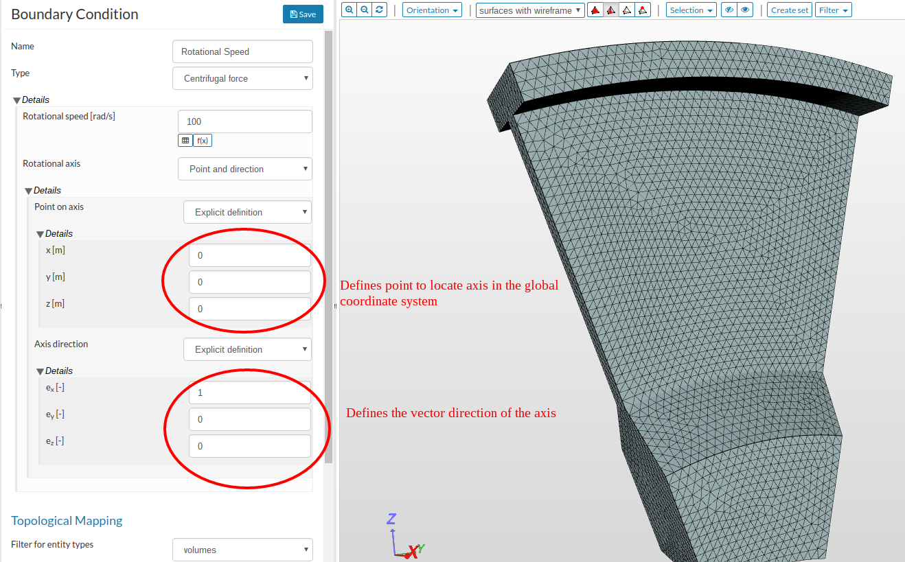
In the rotational speed boundary condition dialog box, the x, y, z define a point int eh global coordinate system that the axis passes through. The point ex, ey, and ez define the vector direction if the axis.
Christopher,
THanks for the reply, I understand this much, what I don’t get is how you know how the model/mesh is oriented to The Global coordinate system. how do you know where (0,0,0) is relative to the model?
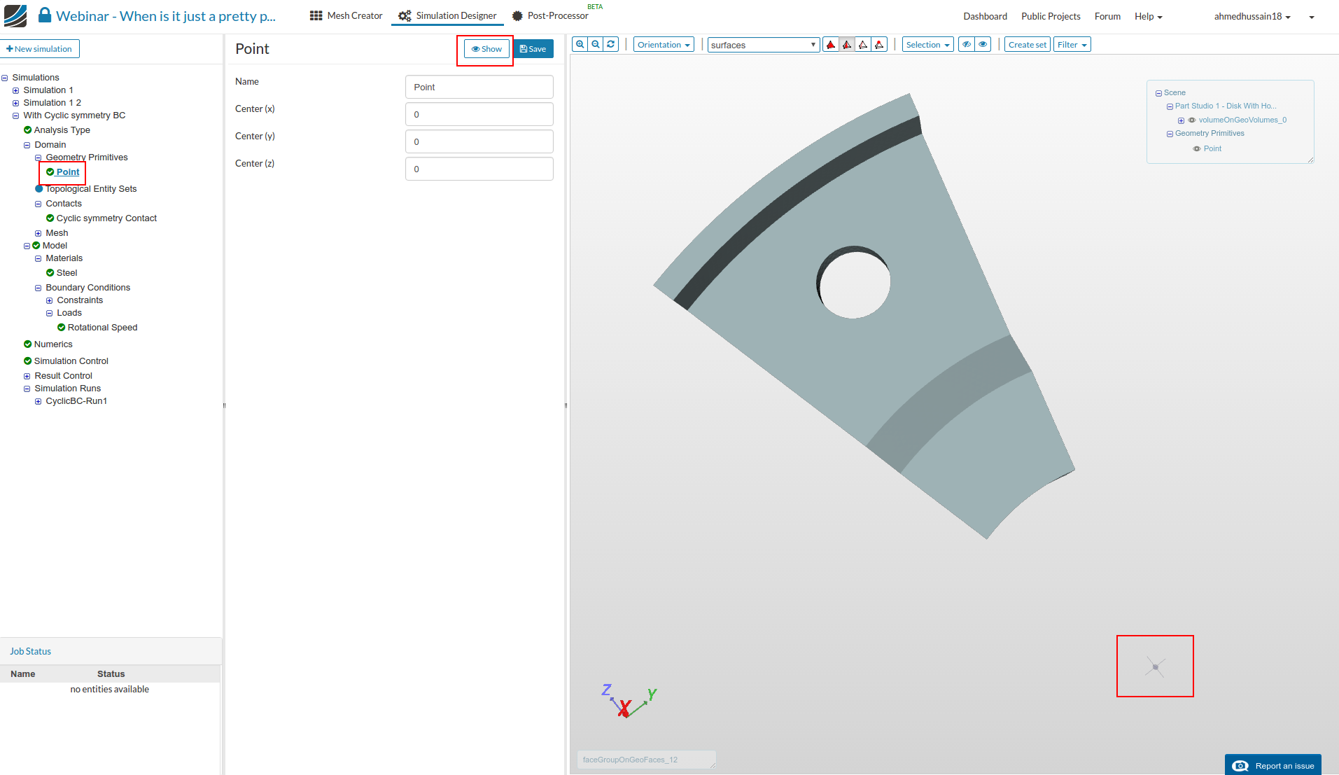
Next, go to rotational load. The rotational axis will be that point i.e. (0,0,0) and rotational axis will be positive x. So it will rotate around positive x-axis along the point (0,0,0).
So I take it you just have to know the geometry of your model to know the distances if say (0,0,0) is not on the axis of rotation you want? Like say I wanted to rotate about the center of the circle as shown further up the part? How do know the coordinates of that center ?