Hey guys,
me and my FSAE team are working in some half car simulations for the past few weeks, but this time,
rather than get the Cd or Cl of the car, we are trying to see the flow inside the sidepod and around the sidewing nn paraview.
The initial ideia was to work with a simplified geometry of our car and using the front tire.
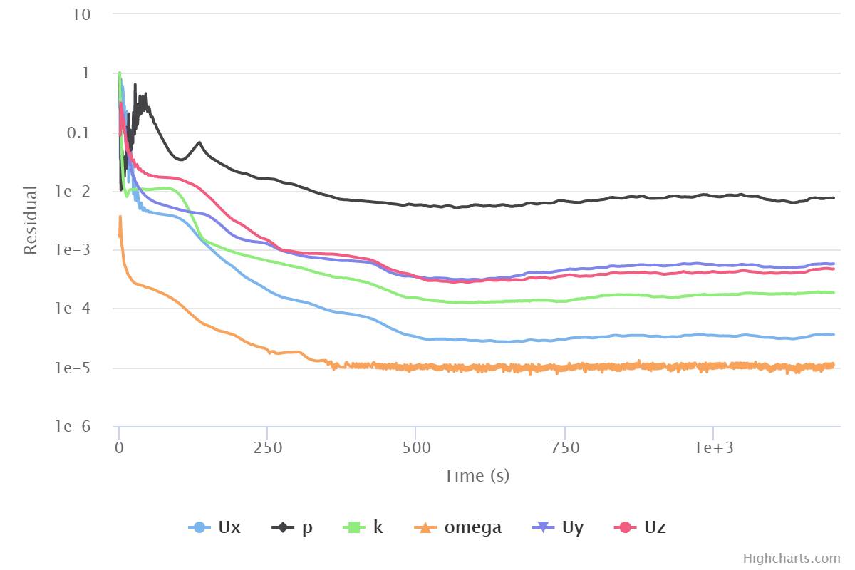
Here´s the convergence and this test is from “Mesh test 4” the “3 layer 1201 ORSI” run
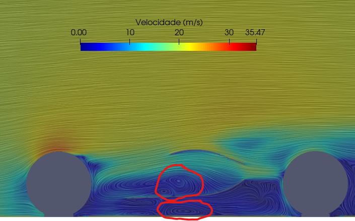
and the surface LIC from the sidepod+sidewing flow
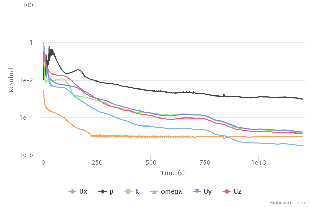
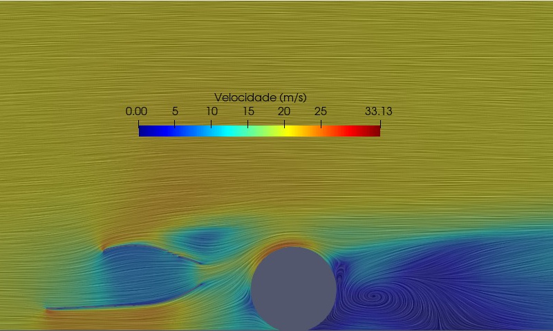
When we first saw these big resirculations we thought it was some simulation bug, or something like that. So to simplify even more our geometry, in order to make a simpler simulation, we decided to take of the front tire to see what happends. So here are the results of the new simulation with just little mesh adjustments: (this is the 3.Layer/2 simulation “Run 1”)
So, here´s the question. After take of the front tire we solve the resirculations inside the sidepod, but one still continue after the back tire and…
- What are we seeing? Is this the wake of the back tire, and in the other simulation, the wake of the front tire inside the sidepod?
-If the surface LIC is a representation of the vectors, correct me if im wrong, how is the vectors going back? In a steady state simulation this kind a make sense, because its a frame of the phenomenon that we are trying to simulate, but when the car moves, in a real situation, the air just doesnt go back. And if our objective here is to see, analyze and quantify the sidepod+sidewing flow, isnt this a transient simulation case? This is our first year making aero and CFD studies so if we are quite inexperienced in steady-state simulations, imagine in transient  .
.
-And here´s the last one: If what we are seeing its not the front tire wake, and shouldn´t be there when we analyze our sidepod flow, does anyone has an idea where i should go or do with this? I don´t think that just taking off the back tire is good enough because i wont solve the problem, i will just stop looking at it (if its a problem).
.
Thank you very much for the attention,
Mateus.
As far as I know, the LIC streamlines simply represent the full data solution set and resolves the velocity vectors in the plane represented in steady state. So, what you see is what you get in terms of airflow, separation and re-circulations.
Whatever geometry is in the volume of air will be what created this airflow pattern.
I think, but I am not sure, those realizations should answer all your questions.
EDIT: Don’t forget to look at flow in other planes of viewing
Hey, Dale.
Thank you for replying so quickly. Let me see if i understand what you are saying… These recirculations are a normal plot in steady state simulations and not a simulation problem? If that´s correct, some questions still bother me. Knowing that this isn´t a bug, its just the representation of the wake/turbulent flow in terms of velocity vectors?
I believe so…
I believe so…
I wish that LIC streamlines had the ability to have direction arrows on them (or not as an option) as they are sometimes hard to follow as far as direction is concerned 
EDIT: In your topic title, you state ‘Surface LIC’ which I believe is incorrect as they do not apply to a surface (unless the surface is the complete plane of the view and then they would be non-existent since all geometry surfaces should be no-slip walls ). LIC plots show with respect to cutting planes/slices through the air volume.
It would be truly great… To cover this issue we are starting to make to two images, one LIC and other with the vectors and trying to compare them.
I see what you mean. But it´s just the option name in ParaView.
Interesting, perhaps they consider the cutting plane/slice to be the surface, I could be wrong altogether…
Well… i agree with you and already change it. I think that you answered all my questions for the moment! Thank you very much, Dale. By the way i really enjoyed that gigantic thread with dschroeder about y+, layer control, ORSI and a lot of other incredible topics. Thank you for that to!
If i want to talk about another subject the correct way is to create another topic, right?
That would be the best way but I think you already know that our long thread did cover a lot though but it was all generally related so we left it that way, live and learn to split when appropriate but that is hard to do…
Hahahaha! You´re right… just checking
The way that you guys did, without splitting it, was amazing, i I loved it! Make the things so easy to connect…
Tagging @yosukegb4 here as well 
Best,
Jousef
Hi everyone !
I’m sorry that I don’t know all of the conversations.
But I just only checked some @ufprformula 's simulations and point out some problems in the simulations.
- Wrong Boundary Conditions
- The wall of the car center should be ‘Symmetry’.
- The floor should be ‘Moving wall’.
- The tire wheels are better to be set as 'Rotating wall’s but these depends on you, because there are some cases for comparing between CFD results and results of wind tunnel tests with no rotating wheels conditions.
- Different Boundary Conditions
- The boundary conditions are different between ‘Mesh test 4” the “3 layer 1201 ORSI’ and ‘3.Layer/2 simulation “Run 1”’, aren’t they? If they are different, there is no meanings to compare the shapes of the cars.
- It is often that some large vortices are created around the car body. Rather, it can be said that we are doing CFD simulations for how to control the vortices by better car designes.
- Of course, you may get wrong vortices by mistakes in simulation methods. It is necessary to check your boundary conditions etc. of your simulations again one by one.
I'm sorry if I pointed out that it wasn't the story of this issue.
Best,
Yosuke
Hi ,yosukegb4!
Thank you to jumping here as well.
I will try to answer all of your questions and appointments. If my explanation isnt good enough you tell me and i will remake the simulations as you say. The hole idea of making 3.Layer/2 simulation “Run 1” was to solve the problem that appear in a even complex simulation, Mesh test 4 simulation “3 layer 1201 ORSI”, in that time i was trying to simplificate my simulation model in order to find the source of the big vortices. So i stop using Symmetry for the symmetry plane, moving wall to the floor, and rotating wall for the tire. I made the tests one by one, removing symmetry and seeing if it works, removing rotations and moviments to see if it works (this one actually do) + removing the front tire, because i was suspecting that these vortices were from the front tire. That´s the true history . The idea here wasn´t comparing the shapes of the cars, it was seeing how much do i need to simplify the simulation in order to see the air entering the sidepod without any issue. After this, im still gonna compare this shapes, but only after i solve this one.
I don´t know if i explain all your questions/problems, if i still miss/im wrong about something please warn me!