So I’ve been trying to follow along with the laser hardening project by ahmedhussain18 and I guess I don’t quite fully understand the heat flux equation he uses. The problem I run into is that I want to do a simulation using a small 56um diameter laser spot size (typical for fiber lasers used in cutting and welding) but it seams that when I get to that scale, the equation tends to 0 for some reason. This could be an issue with how I input the equation.:
((2140)/(pi(0.000025^2)))EXP((-2(((x-0.00277)^2)+((y-0.0021)^2)+(-z+(0.0381*t))^2))/(0.000025^2))
Should I be using the measured spot size as opposed to the theoretical spot size of the laser?
Thanks for any help!
Hey @stone457 and sorry for the delay!
Can you share the project that you use? You can define a radius for the laser, that’s possible. Having a look at your project makes it easier to see what assumptions might be wrong. You can paste the project link as a comment, that’s fine!
Cheers!
Jousef
https://www.simscale.com/projects/stone457/tm_seam_weld/
Hope the link works,
I’ve been messing with it some more so right now it has a larger spot size,
When I go below 1mm the simulation seams to pulse, kind of weird.
Also if you see anything else in my project thats not set up right, mind letting me know, I’m fairly inexperienced in FEM
Thanks for the help!
Hi @stone457!
The setup looks good but I would not use a fixed support, you can simply work with your surface heat flux that is sufficient in my opinion. And no worries, you’re at the right place for learning FEM! 
The spot looks “good” at the beginning but then drifts away at the end, I would have to check why that’s the case, maybe just a small adaption in the formula and it will work like a charm  Might take a bit though, so please be patient. Also quite curious what this application will be used for? Are you working on a thesis or project from your university?
Best,
Jousef
By removing the fixed support, I get an error saying I don’t have a sufficient set of constraints. How would you suggest I set up my contacts between the block and anvil?
Also, the current laser spot size I have in the simulation is 650um which seems to work fine, but with a simulation at 56um, it looks like the heat flux and temperature pulsates. I haven’t seen any drifting in the path like you suggest.
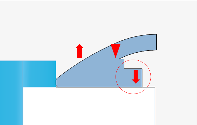
The purpose of this is to simulate distortion on the circled feature in the attached photo with different materials for the heat sink (steel vs copper). The arrows point in the direction that the part seems to distort in real world with the triangle representing the laser weld.
I’m not sure this will give me what I want, but I always wanted to dip my toes in FEM so I thought I would give this project a try.
Thanks for the help!
Hi @stone457!
Having a look at it later on, please be a bit patient 
Cheers!
Jousef
Hi @stone457
Your simulation has really grabbed my attention. But few things are not clear to me at the moment.
- I don’t know where is the laser spot
- Does the process that you want to see come during the time of welding? or due to some other phenomenon
- Can you please describe the CAD for me as I am having a hard time to identify what each solid corresponds to.
- Is there any filler material involved in the welding process?
Thanks
Ani
Thanks,
I’ll try and clear some stuff up for you,
-
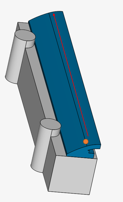
In the attached photo, I have an orange spot which would represent the laser spot, the red line represents the the lasers path along the seam during the welding process.
-
If I understand your question, I’m trying to simulate distortion in the part that results from the thermally induced stress and strain on the part during the welding process. In real world trials, the circled part in my earlier post seems to permanently kick out in the direction of the arrows. I would like to replicate this distortion while the part is on the steel block, then see the difference with a copper block. This was my main intention but wasn’t sure if I would get that far as I’m just trying to understand the software and see if I could get something working.
-
this is a two component part (but it is represented as a single dark shaded model in the attached photo) that is laser welded along the seam. The 2nd model (the light shaded block) would be the fixture the first part rests on (block made of either Cu or Steel). I should also mention, I only have half the models shown as it is a symmetrical set up along the length.
-
No, this is completely a completely autogenous weld
Thanks again for the help,
Hi @stone457
Thanks for your explanation. Now that I have understood your case properly, I can look at the problem involved in this project tomorrow.
Thanks
Ani
Hey @stone457!
Thanks a ton for your detailed explanation again, quite busy at the moment but I will definitely have a look at your project as well - just to let you know you are not left alone. Ani is here as well 
Cheers and thanks for your patience so far!
Jousef