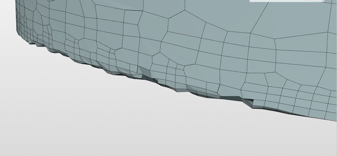
So, i have been playing with the Hex-Dominant parametric Meshing in order to create refinement regions so I use fine cells only in the regions I need in hopes of less computational time and size. But before I get into that I have been trying to get a rough mesh going. However, I seem unable to get the mesh to map around the part on the edges for some reason. I tried a feature refinement and it made some improvement but I still get the pattern shown below. I rather not increase the number of cells in the bounding box discretization because that sort of makes the the whole meshing regions pointless if the whole piece is finely meshed. Is there any way to fix it? I tried changing the scale of snap control tolerance and I also played a little bit with the minVol but I am still unable to get it right. I would appreciate any suggestions you have.
generally, I never use an explicit feature refinement - I always stick with the implicit feature refinement and tune other settings of the mesh operation to get a good result. There is one case with very sharp angles, where it needs extra attention to get the feature nicely resolved - in the rest of the cases simply bumping up the refinement level close at the edge will give you a good result.
But to be sure, could you also post an image of the geometry / CAD model of that region? Then I could provide maybe a better tip.
Thanks for all your help. Your previous comments regarding dealing with castellated cells have really helped me. I have tried making the changes separately but I don’t seem to get it quite right. If I lower the snap control tolerance, the edges seem smoother but with a fillet. Increasing the refinement level on the edge refinement doesn’t seem to help but rather add noise. I was able to create a nice tetrahedral mesh which didn’t have these issues by importing multi body parts and have each local volume refinements but unfortunately that kind of operation does not support multibody mesh/interfaces during the actual simulation from what I could perceive.
Here’s a better look at that same edge shown above. You can see that cracking look on the edges.
In CAD, split the stl file into multiple files each containing surfaces that share important edges you wish to capture (such as the two circular ends that are perpendicular to the shell on a cylinder ), and joint all the stl’s into one. Mesh that joint stl.
mhm - it’s really hard to say without seeing the geometry of that part. The edge you’re not happy with, is it a simple 90° degree corner, so that part is basically a cylinder? Or is it a very sharp corner, say <20°? If it’s a normal 90° corner, I don’t understand why this makes problems, I’d really would need to take a closer look. If you can not share it publicly, you could share it with the SimScale support - that way an applications engineer could take a close look and give you direct advice.
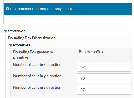
One hint though: The cells seem to be very stretched / long. Did you check the bounding box discretization:
The number of cells in x, y and z - in relation to the bounding box, do they really result in cells with the same edge length? Looks to me if they are stretched in x direction.
Hi @dylan, thanks for helping out. I did use a STEP file to upload the geometry. I guess that didn’t work too well (although it does it perfectly when doing tetra). I am unfamiliar with STL but I will play a little with it and see if that makes a difference, worth the try!
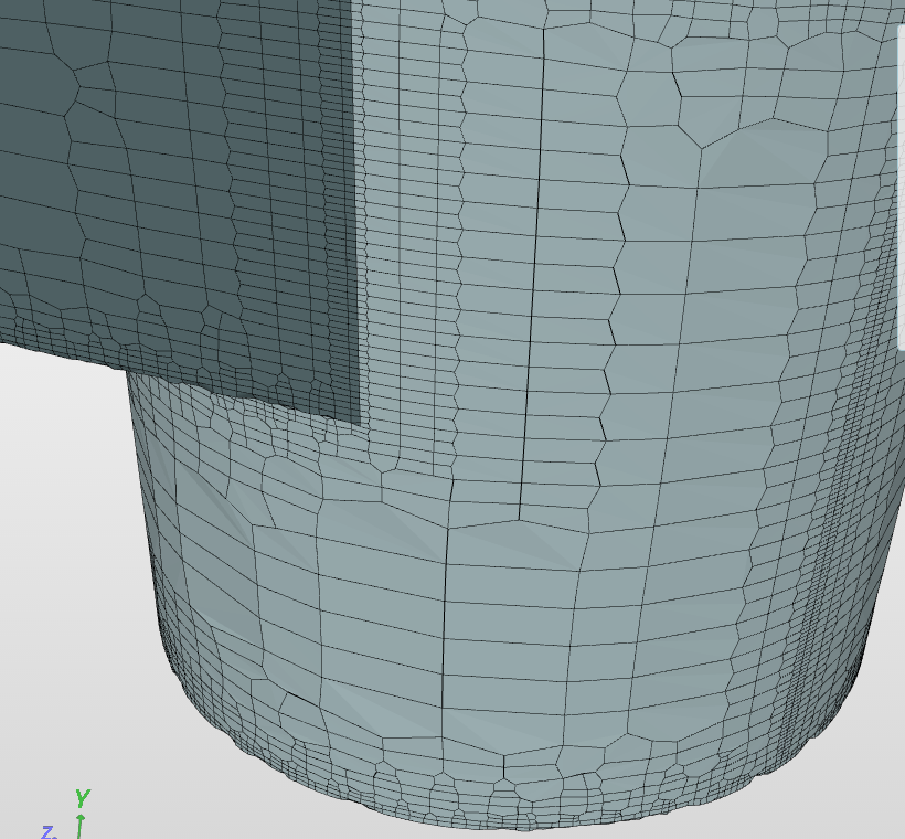
@dheiny, thanks for your input. Really the edge issues happen at most edges that show a corner of lets say x<150 degrees. In the first picture it is a zoomed in version of the bottom cylinder of the second picture so its basically the bottom of a pipe of 90 deg. Unfortunately this is a private project but I will try to share with support. If an answer is found that way I will update the progress here for future readers running into the same issue.
Also, that’s a good call, I did pick all directions to have the same number of divisions. I guess in my mind it was something like specifying the edge length for each cell given a direction. I will correct that as well!
So, I am trying to understand the STL approach. It seems like your suggestion is to break up the CAD into a multibody part? I have done that and meshed it and it works great for Tetahedrals. However, I do not know how to create interfaces in the simulation for the different zones to communicate with each other.
I use solidworks and there doesn’t seem to be much editting that can be done to a STL file. Maybe what you are suggesting is to split and save each body as a separate STL and then merge all the STL files into one. That could work, but I am unsure of how to merge the STL files together.
Now that I know you were using a step file, I believe the problem lies not in the CAD geometry but somewhere in mesh settings.
But… to use a joint stl since you asked:
export into .STL files ( they are in .STL from solidworks )
click open an .STL file with a text editor and you will see the first line starts with ‘solid name’. The last line ends with only ‘endsolid’. Copy and paste the ‘name’ in ‘solid name’ into the last line so that it becomes ‘endsolid name’. Do the same for all the .STL files.
If you have linux, you can use the ‘cat’ command. If you are on windows, you can copy and paste the content of each STL file into an empty text editor. A joint STL in ascii consists of individual STL’s in order, but this exact order is relevant. For example, to joint name01.STL and name02.STL, you will have in the joint file:
I would still like to find out what went wrong in the mesh generated from a step file, because the stl jointing technique usually requires a coded procedure to automate everything starting from CAD, or it will become a time-consuming practice on non-trivial geometry.