Yes.
A Peltier device or thermoelectric cooler (TEC) is an electrical device that uses electrical energy to transfer heat from a region with a low temperature to a region with a higher temperature. It functions as a heat pump.
Generally, users get TECs from a supplier and use them in their modules for cooling. SimScale comes into play when they want to check if TEC can extract enough heat from the components. The manufacturer or supplier of the TEC provides a datasheet with information that we will need to consider when setting up the simulation. Below in Fig. 1 is an exemplary data table for a TEC. The relevant data is highlighted inside the red box.

Fig. 1: Datasheet of a thermoelectric cooler. Inside the red box are the data highlighted that are relevant to a simulation in SimScale. Source: TEC Microsystems FAQ
The column on the very left provides the approximate temperature of the hot side of the TEC or the ambient temperature T_\mathrm{hot} . Each row shows the maximum possible heat transferred Q_\mathrm{max} and the maximum possible temperature difference T_\mathrm{max} across the TEC for a given temperature at the hot side.
Workflow:
- Delete the thermoelectric cooler from the CAD model so that the contact surfaces of the TEC with the rest of the assembly are exposed. Alternatively, you can hollow out the interior of the TEC.
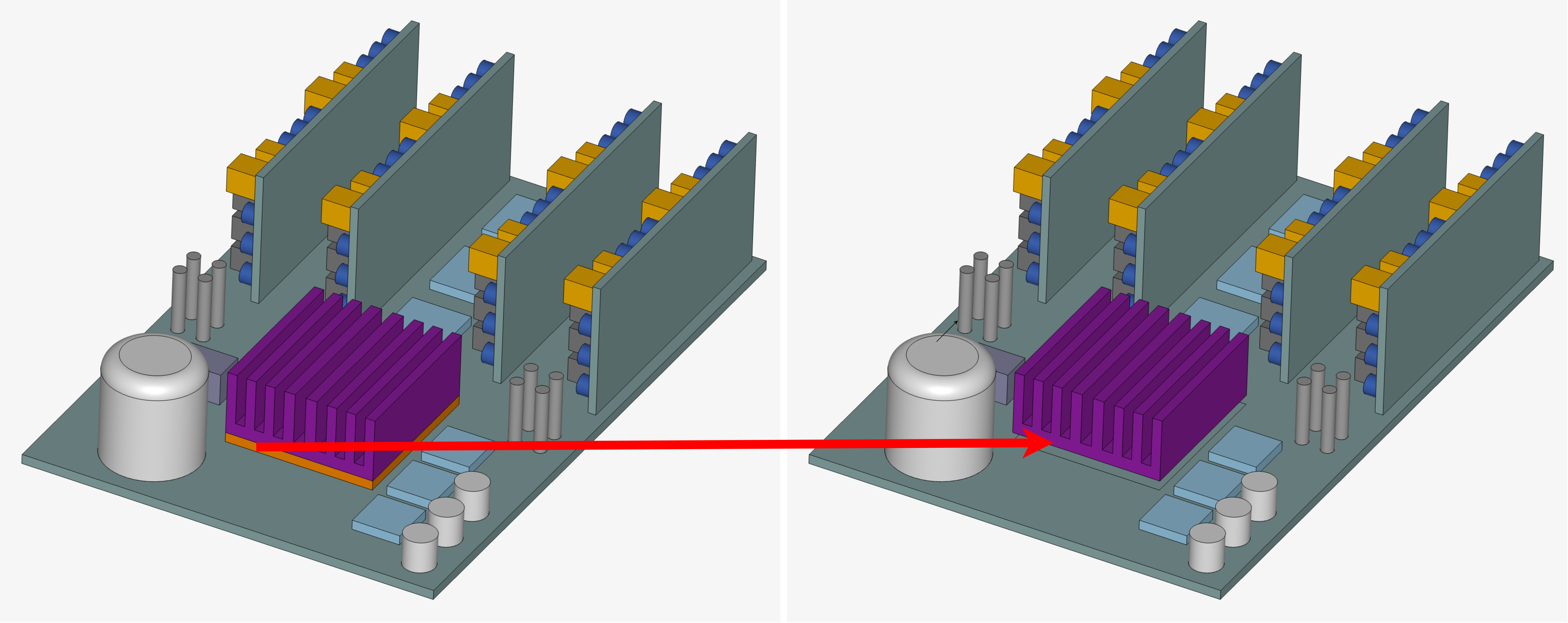
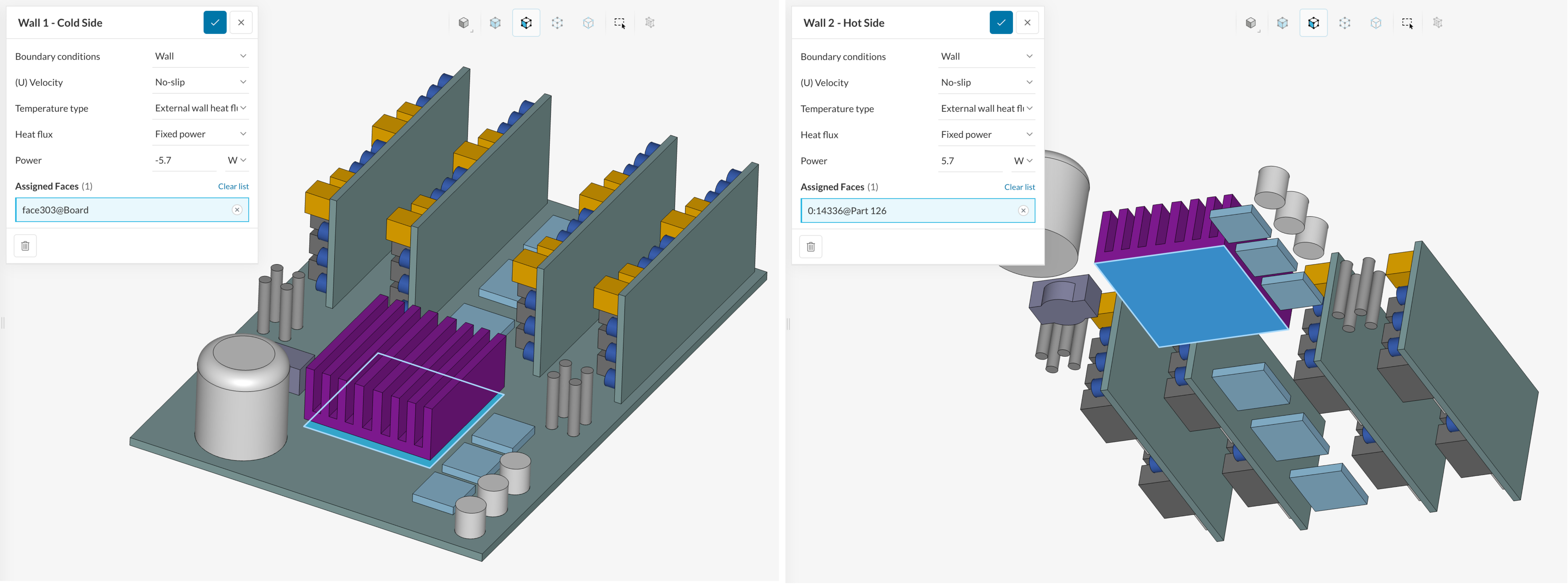
- Apply a wall boundary condition on the contact surface of the cold side with a negative heat flow in W or negative heat flux in W/m2. A negative heat transfer is a heat sink, i.e. heat is extracted from the selected surface. In the case shown below (left image), we apply -5.7 W on the cold side (left image). Similarly, +5.7 W are applied to the hot side (right image). The same heat that is extracted from the hot side is inserted on the cold side. That way we guarantee that energy is conserved. We apply the maximum heat transfer power for a hot side temperature of about 50 °C.
-
After the simulation is complete, you must check what temperature difference has been calculated between the hot and cold side. It must not exceed the maximum temperature difference T_\mathrm{max} provided in the datasheet. If the temperature difference is below that threshold, then the simulation is complete.
-
If the calculated temperature difference is higher than the maximum permitted temperature difference on the datasheet, a second simulation with a lower heat transfer power must be started. For the case considered here, T_\mathrm{max} = 47 °C. The temperature on the hot side is around 51.5 °C, while on the cold side it is -6.4 °C (see Fig. 4 below)
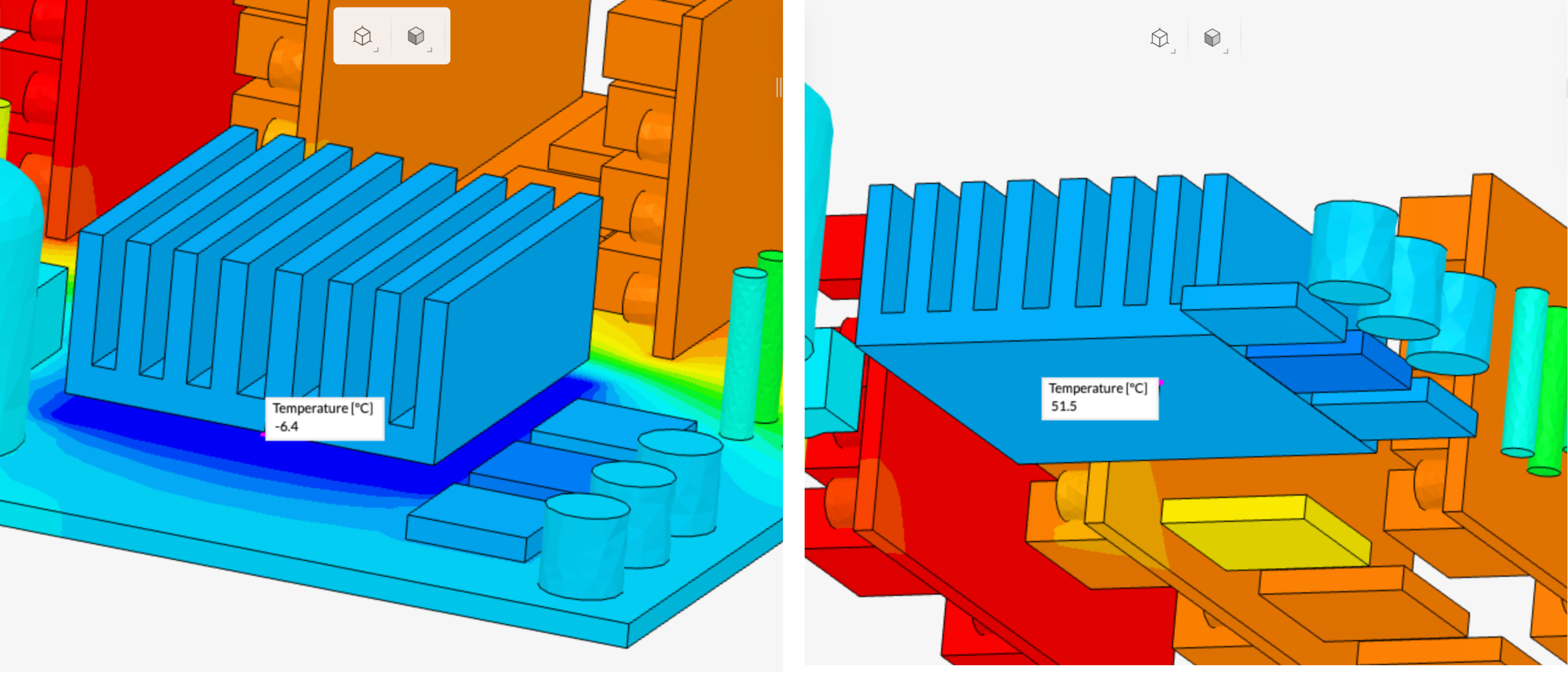
This results in a temperature difference of 56.9 °C well beyond the maximum possible temperature difference. Therefore, another simulation must be started with a lower heat transfer power across the TEC. In this simulation, we start a second run with 4 W instead of 5.7 W. The temperature difference in this run is only about 45 °C. Thus, the simulation is complete.