This forum post is an attempt to familiarise the user with all available menu options which help in effective use of SimScale viewer for simulation.
The main parts of the viewer are:
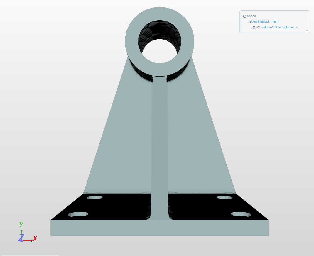
1) The main display
2) Top menu bar
![]()
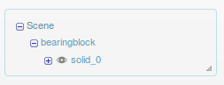
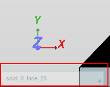
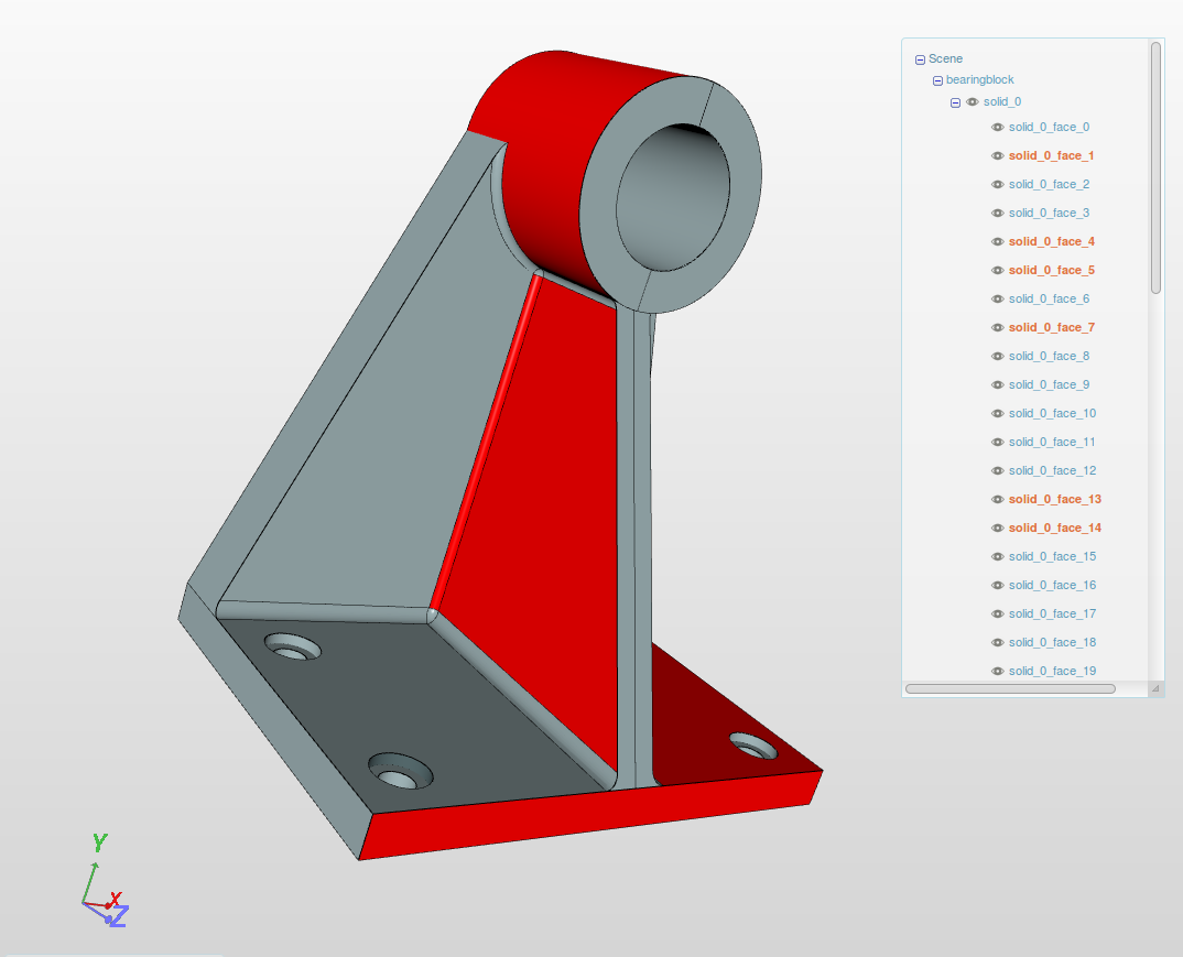
3) Scene viewer - Contains list of volumes and faces.
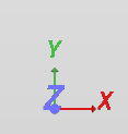
4) Coordinate axis
5) Pointer status - Shows the name of the face or volume where the pointer is hovering.
Navigation
Let’s first begin by navigation. In this section we will discuss some of the basic navigation operations like zoom, rotate, changing the anchor point for rotation and resetting the view.
-
Rotate: For rotating the view, hold the left button of the mouse and move it around in the viewer.
-
Zoom: To zoom in or out, hold the right button of the mouse and move it . Alternatively, you can scroll up or down.
-
Pan: To pan the view, hold the middle button of the mouse and move it around the viewer.
-
Changing origin of rotation: The default origin of rotation is set to axis origin of the geometry. Sometimes it is very convenient to rotate the view about a certain face. In order to do that, hover the pointer on the desired face and double click. The anchor point for view rotation will be pinned to that face at selected location.
-
Reset: If you want to reset the view to the default view, click on Reset view button in the top menu bar.

-
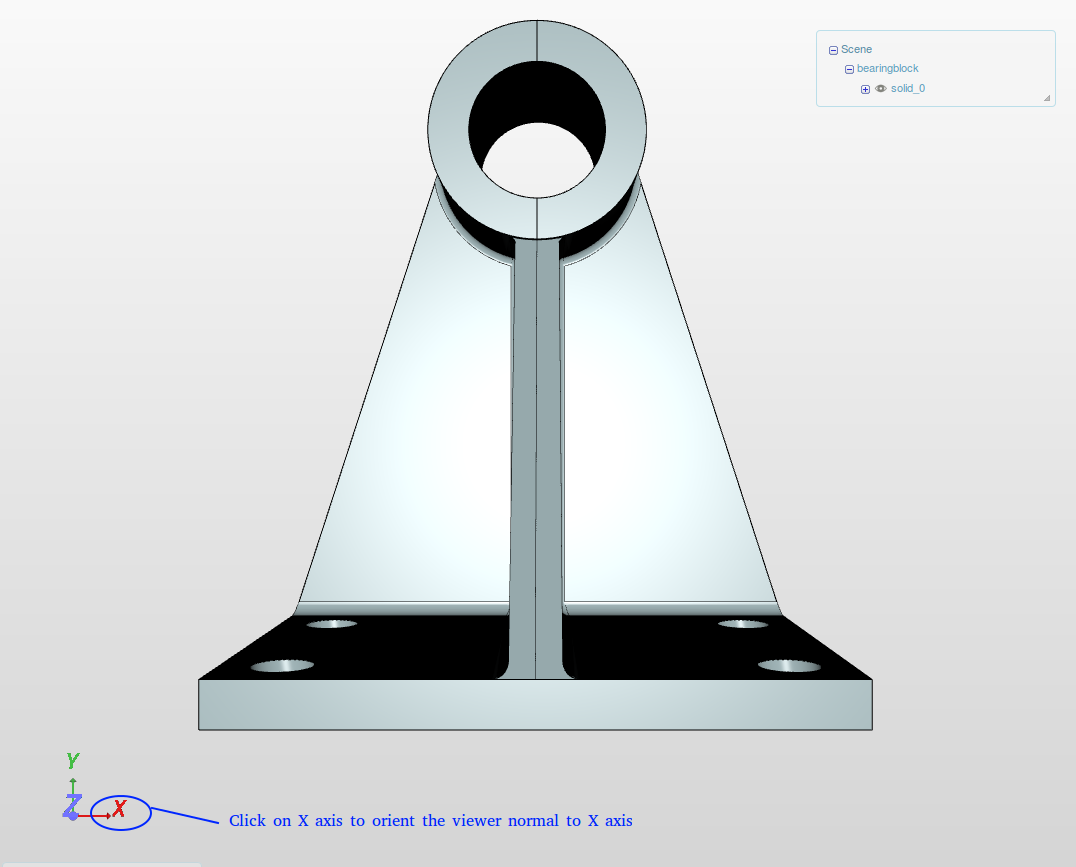
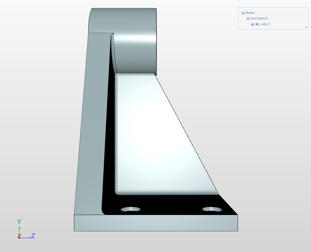
To set the view using particular axis, just click on the the desired axis and the view will be oriented normal to it.
Selection of entities
Selection of faces or volumes is perhaps the most used operation to assign boundary conditions or contact conditions during simulation set up. In this section, we will discuss how to select faces and volumes in the viewer.
-
Volume selection: To select a volume, change the selection mode to Pick volumes by clicking on
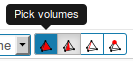 button in the top menu and then hover the mouse over the volume you want to select and then click it. The selected volume will highlighted.
 -
Face selection: To select a face, change the selection mode to Pick faces by clicking on
 button in the top menu and then hover the mouse over the face you want to select and then click it. The selected face will be highlighted.
 -
Alternatively, you can click on the volumes or faces in the Scene viewer to select them. You can also use the Scene viewer to keep track of the selected volumes or faces.
Hide/Isolate/Invert Selection
These operations are useful when the geometry is an assembly of several volumes and some of the faces are not visible in the default view.
-
Hide Selection: You can hide faces or volumes by selecting entities and clicking on Hide selection button
 . Alternatively, you can toggle visibility by expanding Scene viewer and clicking on the eye button at the left side of the entity you want to hide/show.
 -
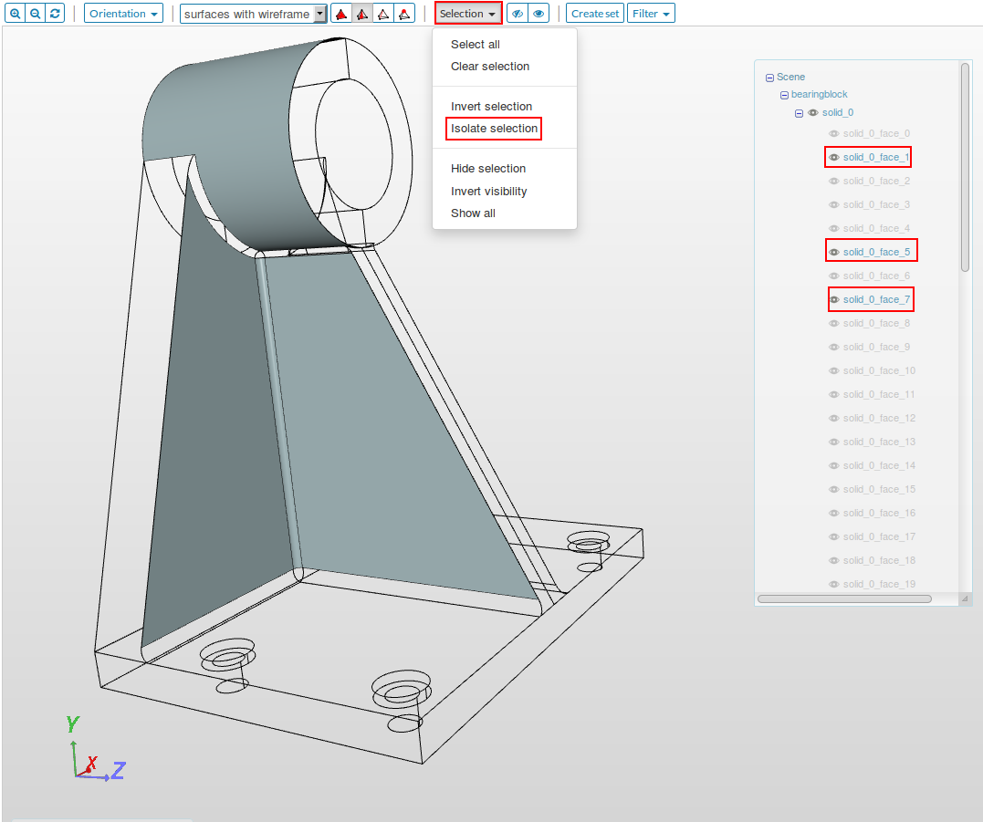
Isolate Selection: Sometimes, your geometry may contain small faces/volumes which are part of a topological set or boundary condition and you may want to check if you have missed some faces/volumes. On clicking the set, all the member faces/volumes will highlighted, but if the faces/volumes are very small and are hidden behind some other entity, using this option will be very helpful. Select the set/faces/volumes and then go to Selection drop down menu in Top menu and then select Isolate Selection.
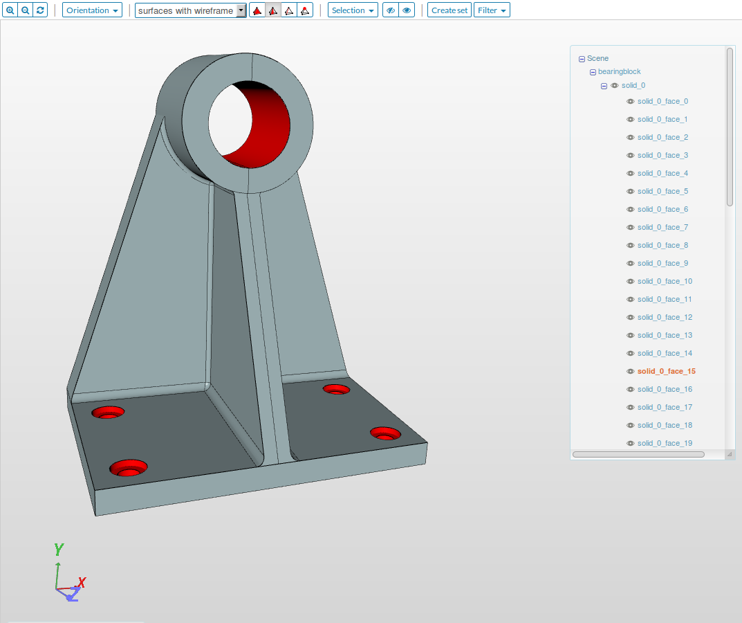
- Invert Selection: This option is particularly useful when you want to select some internal faces that are not accessible. To do this, first isolate the volume which contains the desired face. In the figure below we have only one volume, so it is not required. Now select the faces which you don’t want to select (external faces) and then go to Selection drop down menu in the Top menu and then select Invert Selection.
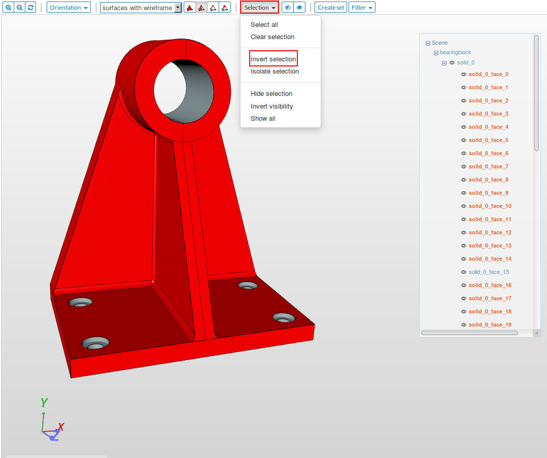
- Alternatively, you can hide all the external faces and can use Select all option in Selection drop down menu.
- Clear Selection : This is used for removing all the selected entities from the selection list, so that you can start selecting entities from start.
Note: When you use selection option like Select all and Invert selection only visble entities are selected.
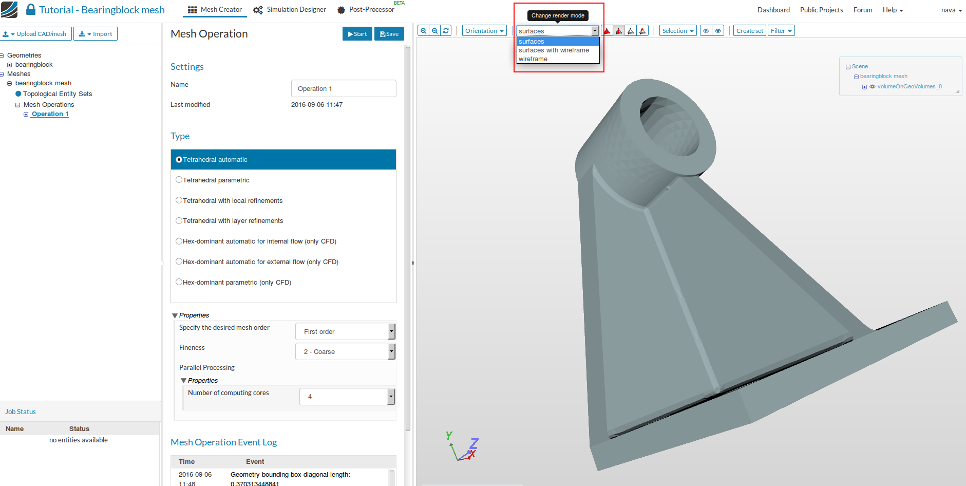
Change Render Mode
There are three types of render modes available in the platform:
- Wireframe: View with only edges
- Surface with wireframe: View with edges and surfaces. Useful when you want to view the meshed geometry.
- Surface: View with only surfaces. This view is very useful when you want to use the meshed geometry but you don’t need to see the mesh. This view takes less rendering time and therefore is preferred during simulation set up while assigning faces or volumes to boundary conditions or contact constraints.