Initial Values for Turbulence Coefficients

No problem!

So how can I calculate or find the value of this so that I know I am within the 0.1-2 range?

Hi @dylan and good to see you back!

The SA 1 equation turbulence model is adapted for flows around an airfoil and as you know boussinesq approximations to not behave super accurate (whatever you define as accurate in this case), but a contracting section is a good example as the eddies loose their identity along the way. And standard k-epsilon is by definition not realizable (need a separate post to explain what that means) so one usually uses realizable k-epsilon but fully developed pipe flow for instance work pretty well with standard k-epsilon. k-omega SST does a pretty good job and there is no need for SA model, what do you think?

Best,

Jousef

Wow, Sydney, Florida and Germany all at the same time :smiley::smiley::smiley:

From Spalart and Rumsey, you have

image

Calculate k and omega using a length scale of your choice.

From this link Turbulence free-stream boundary conditions -- CFD-Wiki, the free CFD reference, you have
image
where,
image is the turbulent viscosity ratio;
image is air density;
image is dynamic molecular viscosity of air (not kinematic).

1 Like

@jousefm

I exclusively use SpalartAllmaras, RealizableKE, and SST as RANS. In fact, I find SpalartAllmaras very useful for external aerodynamics with mild separation, such as a plane or a wing. I think @DaleKramer’s problem can be very well solved by SA, because I have done similar projects.

Aha, I finally see it, I can just back it out from known values.

And this means I really need to go to bed now … Thanks.

Dale

Hi @dylan,

I totally agree here but as SA is not implemented on our platform we have to work with another turbulence model.

Best,

Jousef

@dylan

Just curious as to why you suggest calculating ut/u from the cfd_online.com formula rather than from the Spalart and Rumsey recommendation of 2e-7 * Re ?

There is a 20% difference in my case.

And by the way, I did have to change my reference length from a fuselage length of 5m to a value of 2m to stay in your suggested ut/u range of 0.1~2. My ut/u value is now 1.89 (EDIT actual value is now 1.6182, see edit 2 posts down).

Dale

Did you use the same length scale in Reynolds number?

Yes

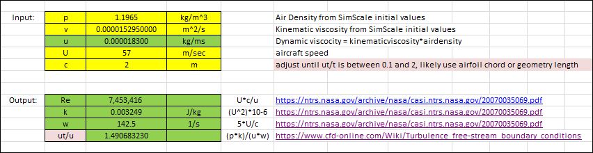
EDIT: corrected the value for u (dynamic viscosity) which is equal to SimScale Kinematic Viscosity * Density

This makes ut/u smaller than the original post…

2 Likes

The 2e-7*Re is just an estimation. The actual nut calculated at inlet should return a nut/nu = 1.888 or much closer to 1.888. I don’t think a length scale of 2 or 3 will lead to much difference in Cd or Cl. It is safe to use what you have here.

2 Likes

Turbulent viscosity and eddy viscosity are the same thing. However, nut = mut/rho, where nut is commonly used in incompressible flow, and mut in compressible flow.

2 Likes

Hey guys.

Could you help with this? I think it might be related.

Hey @bdewar!

Is this related to a problem you have with a project on our platform?

Best,

Jousef

Hi @DaleKramer,

I hope you are doing well. I would like to know, is it okay if my ut/u ratio is equal to 0.1005 ? or Should I adjust any further ? My case is more or less similar, I am running a simulation of flying wing aircraft.

Kind regards
Mohammad Fozan

@dylan what’s’ your take on this ?

here what’s C? Is it the speed of the sound?
I need to find turbulent viscosity ratio for my SA model. Here my velocity is set 30 m/s.
please help me!

what did u consider as C in his equations?

If I use C as my Chord length, 0.15 m I get turbulent viscosity ratio as 0.0735. Is it fine for my model??

@vinulfernando c is the length scale (m) (in my case, I used length value which is slightly greater than the aircraft length), adjust c so that the ratio will be above or equal to 0.1.

1 Like