I believe that this question might be more towards OpenFoam use than SIMSCALE but I figured I would swing it by the community and see if you could help. I am having some issues related to convergence of a K-W SST model and am in the process of checking my BCs and ICs. So far I was having good convergences in laminar models and so I believe that the BCs and ICs not related to turbulence are probably fine. This leads me to examine my K(initial) and W(initial):
The first question I have is, what is your approach to obtaining a value that would be good for the whole domain? Do you take your lengths from an specific location? Calculate values at different points and try to average them? I am more used to prescribing the values at specific locations (BCs) and allowing for the ICs to be calculated automatically.
My second question is what approach do you use to obtain the actual values for K and W? I generally follow something like what is shown in the webpage below:
there are several CFD engineers in the forum that might be able to give good hints here (e.g. @anon5767293, @jprobst, @anon62721193, @pfernandez). My 2 cents: Depending on the application at hand, I also use such correlations you posted - so that’s a valuable approach (I’ll try to post more links soon but I’m traveling right now).
But as a side note: The initial values of your turbulent quantities do have an impact on residual convergence, but they are only one factor. The values might actually be fine, but e.g. mesh, numerical schemes or solver settings might need some tuning. Are you working in a public project? That way I could take a direct look.
I usually use the tools you have mentioned, but bear in mind that those equations were developed for pipes. Thus, you may also use the reference length of your object in those equations (e.g., the chord of the airfoil). In internal engine applications we use the average piston speed and the cylinder bore as references.
Initial/Inlet turbulence is not easy to define. But you also want to pay attention to the sensitivity of your results to these inlet values. Some models are more sensitive than others in a number of flow fields.
There are a number of ways to define inlet turbulence, some involving the use of free stream Mach number and speed of sound etc. You can refer to NASA’s turbulence modelling resource for more information.
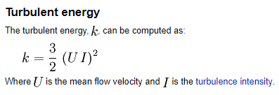
The equations listed above are for fully developed internal incompressible flow. To use an omega-based model in such case, you want to provide (inlet turbulent intensity) I and an (estimated length scale) L. The value I and (turbulent kinetic energy) k are calculated by the two equations you wrote down. To calculate (turbulent dissipation rate) epsilon, use the mixing length formulation, because OpenFOAM uses mixing length: . This also means L is 0.07*(hydraulic diameter). Now that you have epsilon, you can go ahead and calculate (turbulence frequency) omega, again using the mixing-length formulation.
Note that this way the (turbulent viscosity ratio) nut/nu at inlet will be very large, which is reasonable for fully developed internal flow.
It is more difficult to define inlet turbulence for external flows, because now the length scale can be less obvious, and sometimes you might need to define a very large omega at inlet so that nut/nut is small — for a clean inflow with negligible turbulence, the ratio nut/nu should be a small value, meaning the laminar viscosity is dominant. Such flow fields are typical when computing external flow with a fairly large domain ( not in a wind tunnel ).
In terms of the instability of your model, omega-based models tend to create less turbulent viscosity than standard k-epsilon around the wall. This is one of the reasons why omega-based models can produce more flow instability in the wake for external flow, and as a result, forces fluctuate a lot. If you increase inlet I and/or nut/nu, the omega-based model will have a more stable wake. If you can’t introduce more turbulence at inlet, you can take the time-average of those force values or switch to a different turbulence model.
Thanks guys, I am glad to know that I wasn’t so far off from my original assumptions. It seems like using the inlet values as initial values in the entire region is an ok practice for most cases and, from my understanding, the default values should always be replaced by the calculations. @dheiny I am working on both public and private projects, most of my work being for internal flow applications.
if you have checked your boundary conditions, initial conditions, solver settings etc and are still facing convergence issues, the most likely problem might be the mesh. Depending on how complex your geometry is, if the mesh is not refined in key regions (eg regions of high expected flow gradients), the solver might face convergence issues or in some cases might also end up giving physically wrong results. Now, the algorithms in OpenFOAM are flexible with mesh quality ie they are able to handle relatively bad/coarse meshes, but not in all cases. Checking mesh quality is essential and the mesh log gives a fairly detailed output on that. It is also a good idea to visually check the mesh in key regions to make sure there are no cells that are bad quality (highly skewed or stretched, for example). Usually, good quality meshes ‘look’ good!
+1 on the mesh. How far along does the analysis get before it diverges? Since (I assume) it is a transient analysis, try to view the results just prior to divergence. Look for signs of oscillation, unnaturally high gradients near BC’s/walls, mesh dependence. Also, perhaps try a K-e model first, as it is generally more stable than the K-W.
According to SST k-omega model -- CFD-Wiki, the free CFD reference, K-e is used in the free stream, and K-w is used in the boundary layer. So if you can get it to converge with the K-e turb model, then you know your issue is in the boundary layer. At that point, investigate the mesh near the walls…
I know this is an old topic, but I didn’t provide any reference for external aerodynamics at the time.
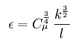
Here is a paper by Spalart and Rumsey, who suggested the following combinations for inlet turbulence when using SST and RealizableKE for external aerodynamics:
where, c is the characteris length of the object. Note that this way the inlet viscosity ratio can be maintained at a small value suitable for external aerodynamics computation.
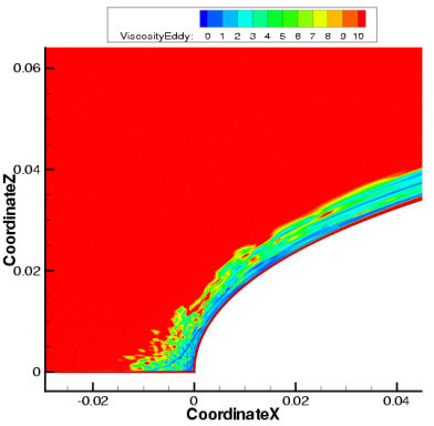
The floor value requires modification to the turbulence models, but I don’t think you need it in OpenFOAM. First of all, the SST model in Spalart and Rumsey comes from Menter (1994), where the turbulent viscosity uses the magnitude of vorticity (Ω) in its definition. A quote from Spalart and Rumsey here – ‘some implementations of the SST model use the strain rate instead of Ω which is neutral in thin shear flows’.
Thanks, I am not too sure if I understand your in-depth references but to me it looks like OpenFOAM may already not let the inlet initial values disappear at the downstream walls as long as they are within a few? reference lengths of the inlet, is this correct?
Also, if you are analyzing a whole aircraft without fancy slots and flaps on the wing, would it be appropriate the use fuselage length as a reference length or something like the MAC of all the horizontal surfaces or the longest wing chord?
@DaleKramer
The SST that uses strain rate to compute turbulent viscosity does not remove turbulence free decay. The advantage of the strain rate formulation is the absence of irregular turbulent viscosity outside of the flow boundary layer, which can occur with the vorticity formulation without controlled decay. See Figure 6 in Spalart and Rumsey,
The purpose of defining a length scale at the inlet is to compute turbulent viscosity. In practice, it does not really matter what length scale is chosen, as long as the turbulent viscosity ratio is not unreasonably large or small Turbulence free-stream boundary conditions -- CFD-Wiki, the free CFD reference. What you can do is start a spreadsheet, and calculate the ratio using different length scales, A ratio between 0.1 and 2 is probably what you want to aim for. Chances are the SST model is not sensitive to the exact number, as long as it is within this range. You can also switch to SpalartAllmaras, which requires merely a nuTilda value at the inlet, usually set up 3 times the molecular viscosity of the fluid. (Does SimScale have SpalartAllmaras?)
I have been using fuselage length for my reference length when I had read the below quote from here :
The turbulent length scale should normally not be larger than the dimension of the problem, since that would mean that the turbulent eddies are larger than the problem size.
It has ’ LES Spalart-Allmaras’, which I have not tried yet because I have not been able to intelligently decide what value of ‘nuTilda [in²/s]’ and ‘Eddy viscosity [lbf s/in²]’ to use for initial conditions (they both default to 0).
In practice, it doesn’t matter what length scale is chosen, as long as the resulting turbulent viscosity ratio is within 0.1~2 for external aerodynamics of a plane, because a plane operates in a ‘clean’ inflow environment, as opposed to a car travelling in the wake of the car in front. Since you have decided to use the length of the fuselage, by all means stick with it (unless the turbulent viscosity ratio is very large). You can calculate the ratio using the formula below, or see Turbulence free-stream boundary conditions -- CFD-Wiki, the free CFD reference
What difference would it make if you change the ratio within that range? Very likely you will see changes in Cd and Cl, but they will most likely shift upward or downward consistently. For example, if you increase the ratio, chances are all Cd values will shift up or down for approximately the same amount. The trend of these values will remain the same.
The LES Spalart-Allmaras model is detached eddy simulation suitable for transient computation, so you won’t need it.
I have seen an I (turbulent intensity) value of 0.01% used for sailplanes and a value of 0.1% used for ‘normal aircraft’. My design is somewhere between them, is the value to use for I, a sort of subjective value?
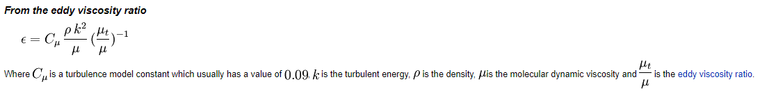
You have shown the formula for e (epsilon), is that not dissipation rate?
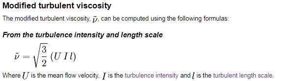
Modified turbulent viscosity, or nuTilda, is for the SpalartAllmaras model. Turbulent viscosity ratio, or eddy viscosity ratio, is nut/nu, or mut/mu
where
nut: kinematic turbulent/eddy viscosity of the fluid
mut: dynamic turbulent/eddy viscosity of the fluid
nu: kinematic molecular/laminar viscosity of the fluid
mu: dynamic molecular/laminar viscosity of the fluid
@jousefm SimScale only has standard-kEpsilon, kOmega, and KOmegaSST as RANS models? I don’t think many people still use kOmega, because SST is a much better option. Why is SpalartAllmaras not implemented as RANS? The standard-KE is probably occasionally used for fully developed internal flow.
I am unable to find a kinematic or dynamic ‘molecular viscosity of air’ or ‘laminar viscosity of air’ to make the ‘turbulent viscosity ratio’ calculation.
In fact, it appears to me that ‘turbulent viscosity ratio’ is dependent only on the type of fluid, so how can it ever have a range from 0.1-2? Shouldn’t I just be able to find a ‘turbulent viscosity ratio’ for air or water etc?
Sorry for being so dense, it is late/early here in Florida …
 . This also means L is 0.07*(hydraulic diameter). Now that you have epsilon, you can go ahead and calculate (turbulence frequency) omega, again using the mixing-length formulation.
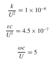

 …
…