A co-miller of mine asked a question around different Roughness Heights for ground planes of External Flow Volume.
But I have a more generic question:
I have an empty external flow volume (there is only a very small object at the end of the volume, to be able to generate a simulation): see Ren trees by nl_victor_reij | SimScale and then ‘Simulations’: Empty EFV.
I used for the ground plane of Roughess height=544m (Simulation Runs: RH=544,Cs=0.9,MS=0.3,CB2) or of 0.0544m (Simulation Run: RH=0.0544,Cs=0.9,MS=0.3,CB2). I see no real difference in the velocity in their respective ‘Solution Fields’.
So why is there no difference between these two very different Roughness Heights (a factor of 10000) of the grond plane of the External Flow Volume? I must be doing something wrong, but what?
Thanks for your help.
All the best,
Victor
By the way I tried many other (more realistic) Roughness Heights : 5, 5.44, 10.88. All the same output.
They are in the same Simulation: Empty EFV.
Hi @nl_victor_reij,
Thanks for posting.
As I see it, we can’t know wether the results are really different since you don’t have numerical data available in your simulation runs. The wall roughness modelling will impact the wall function, where an extra term will be added to take it into account.
That said, you should expect an impact on the boundary layer and perhaps more importantly in the Wall Shear Stress.
Cheers
Igor
One can look at the graphs… And the graphs are all the same…
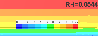
Here is the graph starting some 150m from the inlet (height lines at 3.4 and 6.8m, inlet ABL has z0=0.5m and U6.8=8m/sec):
at Roughness Height=0.0544m (Simulation Run: RH=0.0544,Cs=0.9,MS=0.3,CB2 ):
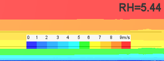
at Roughness Height=5.44m (Simulation Run: RH=5.44,Cs=0.9,MS=0.3,CB2):
And this is RH=5.44 but over the full simulated length (inlet on left side and 165m on the right side):
at Roughness Height=544m (Simulation Run: RH=544,Cs=0.9,MS=0.3,CB2):
5.44m and 544m are very close. There is some difference betwene 5.44 (and 544) with 0.0544m.
Is indeed the influence of Roughness Height soo small???
I have the feel I have my CFD parameters somewhere wrong…
Any help welcome. Thanks
All the best,
Victor
Hi @nl_victor_reij,
The color gradients are not set and would depend on the limits we set (since numerical data is unavailable, we wouldn’t be able to properly compare). A better approach to measure the influence of the change in roughness height would be to observe the effects on the Wall Shear Stress or Forces, in my opinion.
Cheers
I set the colors by using the limits, so that is not the problem (so the scale is correct). Of course there is a small error due to that and also because I only used a color resoluition of 1m/sec. But that error is not large enough not to be able to evalute things, IMHO.
Anyway I will look into Wall Shear Stress or Forces.