Increasing mesh sizing size

I am trying to simulated an in-situ experiment reported in an article by Nageli
(Nägeli, Werner, Untersuchungen über die Windverhältnisse im Bereich von Schilfrohrwänden, Mitt. Schweiz. Anst. Forstl. Versuchw., 29, 213–266,1953).
He had a 25m long fence of 2.2m (H) height and measured at 22m (-10H) infront (reference speed) and behind the fence at heights of 1.1 (0.5H), 2.2 (H), 4.4 (2H) and 8.8m (4H) and distances ranging from -22 (-10H), 11 (5H), 22 (10H), 44 (20H) and 66m (30H).
All these are also as Cutting planes in below simulations. All measurements are perpendicular and at middle of the fence (x=0m).
So I used for the fence a rectangular block with Perforated plate with free area ratio of 0.5 (at least 4 cells) (2.2250.4m).
I also created an extra Cartesian Block (CB1) to increase the mesh sizing size manully,;CB1 is between -11m (-5H) and 22m (10H).

My project is here:

And here are the SIMULATION and Simulation Run with results (but the side views in below links also show this behavoir of course):
SIMULATION:
25m, 2.2m:5m/sec,F=7.5

Simulation Run:
<x=0, side view, looking perpendicular and at middle of the fence>
<CB1 is from y=-11 (y/H=-5) to y=22 (y/H=10), so larger y migth not be correct>
z0=0.5-op=0.5-VolCus=0.1-Dir=010 <default cell size: around 2.5m> (4)

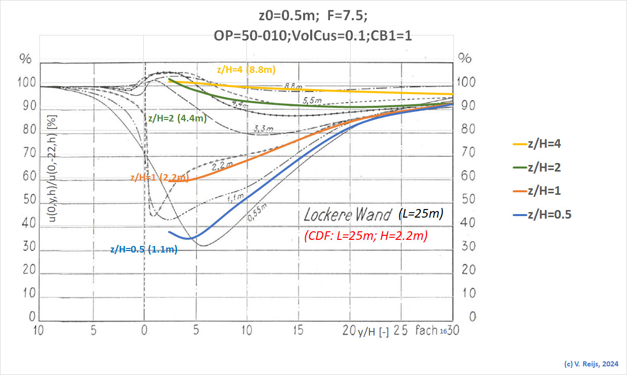
z0=0.5-op=0.5-VolCus=0.1-Dir=010-CB1=1 <cell size: 1m> (16)

z0=0.5-op=0.5-VolCus=0.1-Dir=010-CB1=0.5 <cell size: 0.5m> (15)

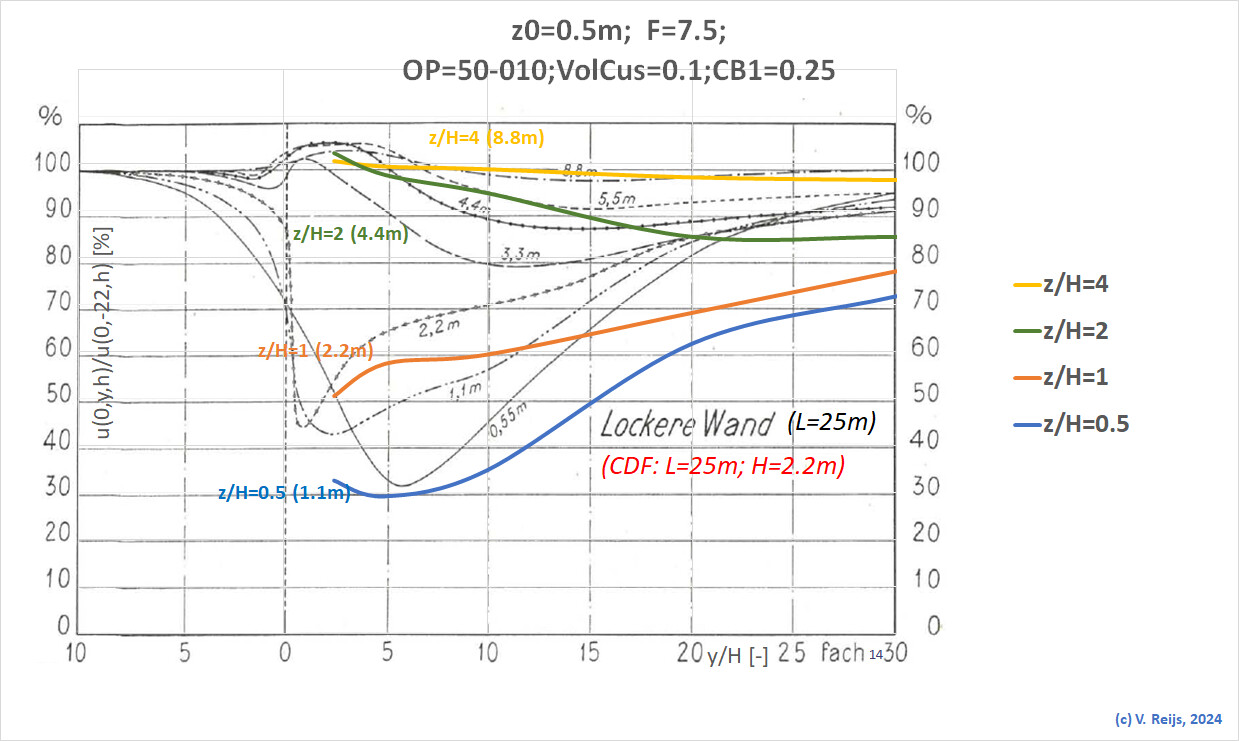
z0=0.5-op=0.5-VolCus=0.1-Dir=010-CB1=0.25 <cell size: 0.25m> (14)

z0=0.5-op=0.5-VolCus=0.1-Dir=010-CB1=0.125 <cell size: 0.125m> (17)

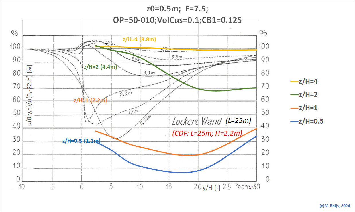
The B&W curves give the data from the Nageli article and the simulation (colored and labeled) are for each height the speed ratio (relative to speed at -10H) perpendicular and at middle of fence.
Interesting that the ones with the least resolution (aka no CB1 [mesh sizing around 2.5m] or CB1 and perhaps also 0.5m) map quite well the B&W results of Nageli.
The more meshing cells (resolution 0.25 and 0.125m) are included, the least matching between the simulation and the in-situ experiments.

Is the simulation further away than 10H [size of CB1] so bad because of the change from CB1 mesh size (0.25 or 0.125m) to flow region mesh size (2.5m)?
<I tried to enlarging the CB1, but then I got memory shortage>

I always thought that the more meshing cells the better it is, but is there some optimum? Aka how best to determine the number of meshing cells per meter?
Or do I do my meshing wrong? Any advice is thus very welcome.

Thanks for your help/feedback/advice/patience.

Hi @jjansman,

Unfortunately we don’t have the bandwith to look into scientific papers to compare with your simulations - have you considered taking this to your advisor?

What we can be sure of is that the finer your mesh, the higher the resolution of your results. Also, SimScale’s porous media model has been validated multiple times and it’s proven to work fine.

Cheers
Igor

Sorry, if you got the impression that it was about comparing with literature. That was not my goal.
I only found that the higher Mesh resolution (only using smaller mesh cells) I use, the stranger (the more diverse) the results become (while keeping all other things the same).

But thanks for acknowleging that the higher the mesh resolution (smaller cells); the better results should be. Need to determine what I do wrong then (unfortunately I have no advisor), as the present results of mine make no sense.

Thanks

All the best,

Victor

Dear support,

A co-miller (at a traditional wind mill) also is working with SIMSCALE. He is using another scientific article to verify the results of SIMSCALE:
Ren, Xinyi et al.: The influence of wind-induced response in urban trees on the surrounding flow field. In: Atmosphere 14 (2023), issue 1010, pp. 1-23.

<just to be sure: we are not really trying to check the results of SIMSCALE and the literature, just to have some ‘nice’ examples>

His results are at: Ren trees by nl_victor_reij | SimScale
SIMULATION: 1EffectiveRenCylinder-blockfar

We have the results here sumurised: Simuate the wind from Ren 'sarticle

He looked at the effect of the mesh default size (DS) in a Cartesian box; so he reduced the mesh default size in steps of 0.1m (from 0.5 to 0.2m). The Cartasian box is around a cylinder towards the end of the external flow volume.

Interestingly a mesh default size 0.5m of the Cartesian box matches a Fineness=9 for the whole external flow voulme (without Cartesian box). This was somewhat expected as the mesh size using Fineness=9 is also close to 0.5m

It looks that a number of cells with mesh default size of 0.4 and 0.3 stays quite the same (around ~4.5M), and the results are thus also quite similar.

If we go to a mesh default size of 0.2m, the results change considerable IMHO!

So what is happening? Do we need to reduce further the mesh default size to stabilise (we were not able to that that in the Community plan)?
Or is the ‘local stable’ situation around 0.3 and 0.4 the best ‘place’?
Why is this results of 0.2m so different?
Or is this due to the Community Plan properties?
So how do we determine the optimum mesh default size?

All the best for 2025,

P.S. This matches somewhat my own experiences with the Nageli fence (using perforated plate porosity),
where a smaller mesh default size is considerable different at a certain size, see the earlier messages in this thread.

P.S.S. In the above models we used a porous medium: one is a perforated plate and the other Darcy-Forthcheimer. Is it perhaps the porous medium that cases this change with a small mesh default size?
Thus in the meantime we are testing this with a non-porous cylinder:
SIMULATION: 1EffectiveRenCylinder-NoPorosity