Hello everybody, as the title says i have a floating point error on a cfd simulation with high flow velocities.
The project is this: https://www.simscale.com/workbench/?pid=2598692630727667007#tab_1-0
I checked other helpful topics related to the problem and i tried to follow the suggestion of using high order schemes. The problem remains.
I’m pretty sure the problem is located in the csv boundary condition. Previously i’ve ran simulation with a velocity inlet of 2 m/s and everything went fine. Then, following some examples here, i’ve tried to upload a wind profile boundary condition as inlet and here i got the problem.
If someone could give a check i would be very happy.
Hi @albesaca, So the main issue was indeed the .csv. The file input a single line of values at the centre, with varying height, however, because we are interpolating the values onto the inlet plane this can sometimes be a bit tricky. What I did was add a line at each edge of the inlet plane. What I should have done was also aligned the ‘x’ position to that of the inlet plane also (when you see my .csv it will make sense).
I also wanted to show how it is easy to create a much more efficient mesh at a fraction of the cost, so I increased your bounding box to much bigger to ensure that results were not affected by the wall boundaries. I then used the beta, automatic meshing algorithm, with a region and layer inflation and got a mesh that is much better but cell count is around 4 million vs 25 million.
The project is run only to 5 iterations to ensure that the issue is now fixed, you should review the mesh and alter to your needs, amend the csv’s ‘x’ values and maybe add more lines for better interpolation and increase run time to convergence.
Good luck,
Darren
Thanks for the meshing tips. I’ve been used to work on grasshopper/butterfly, so my OF knowledge is not so extended.
About the csv file, finally i understood. I really couldn’t find the connection with the coordinates different from z. Anyway, the simulation keeps not converge. I’ve tried with your meshes and with my old one, of course with two different csv.
With your meshes the simulation diverges at time 115, with my old meshes the machine run out of memory.
Hi @albesaca,
You can adjust the numerics with regards to Darren’s mesh. Try lowering the relxation factors, changing the solver to smooth and changing the gradient schemes for default, grad§ and grad(U) to cellLimited Gauss linear if the above mentioned changes still result in divergence.
Also for the diverged run with Darren’s mesh, do you have a link to the project?
Cheers.
Regards,
Barry
This is the log.
I’ll check these other tips, thanks in advance.
I’ve changed the solver and lowered the relaxation factors but i still get divergence.
Hi @albesaca,
Very strange. I suspect the mesh quality is insufficient. The challenge is that we need to keep the cell count low so as to not hit computational limits. I will copy your project over to see if I can get the mesh quality to be better.
Let me ask my friend @1318980. Any ideas as to why it is still diverging?
Cheers.
Regards,
Barry
I wanted to write this too. The meshes which i’m testing are setted on “Coarse”. Unfortunately i’ve tried to increase the quality without any result: the operation fails without any message in the log.
Now i’m trying to make a brand new background, a bit smaller than the one suggested but with the same settings.
Thanks for help by the way
Hi @albesaca, any chance you could send me a geometry in .step?
I’ll PM you my email address!
Cheers,
Darren
Hi @albesaca, let’s try bring the chat back here so it can benefit anyone who might also have an issue.
So I there were two points I was trying to make about the mesh and geometry, and they might not necessarily be the solution but it would make for a better mesh.
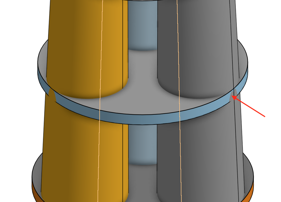
The first point is that the geometry seems to overlap, and although this shouldn’t be an issue, I try to ensure that no solid occupies the space of another, to avoid ambiguity:
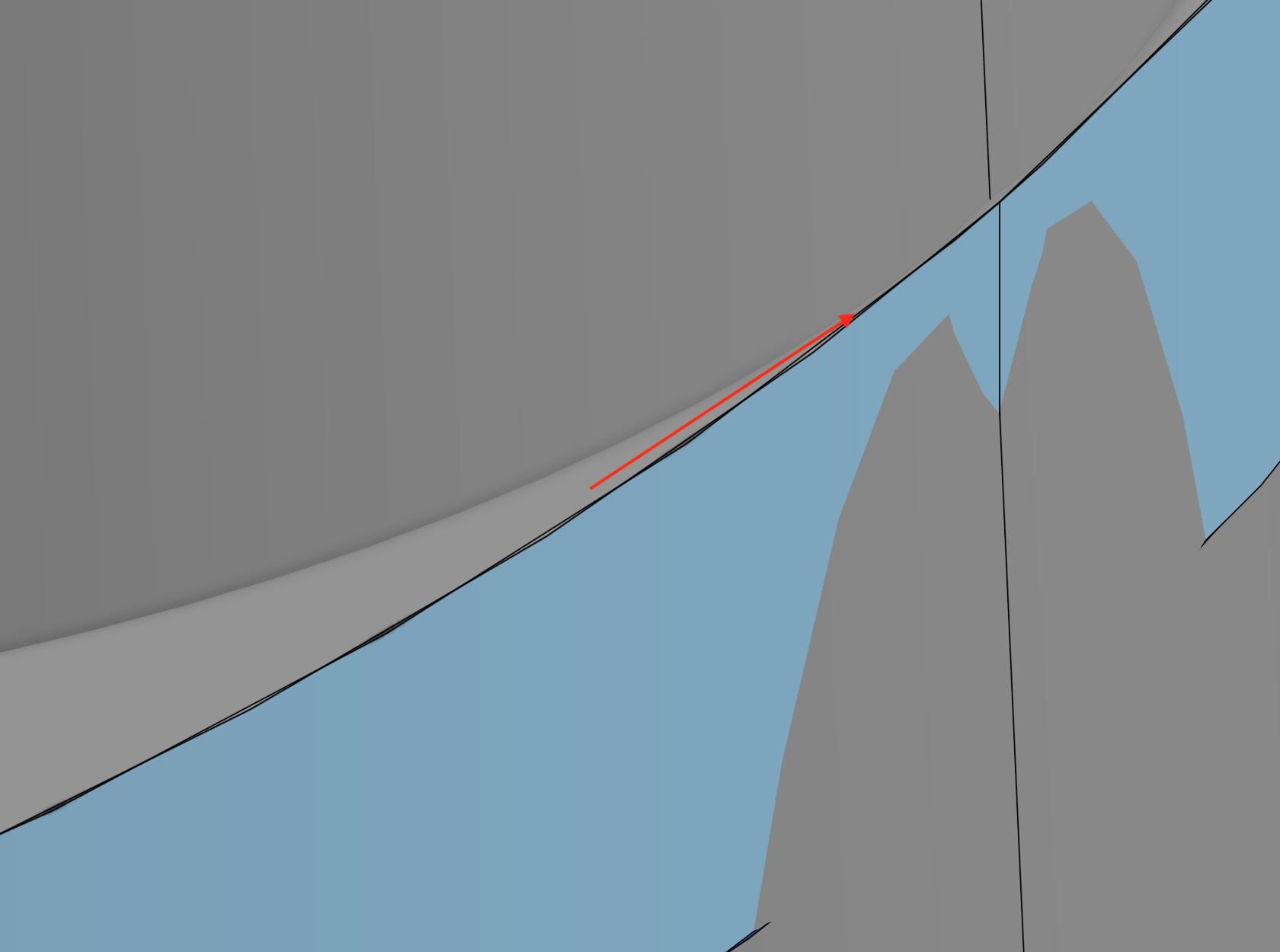
Secondly, there was an intersection that seems to get smaller and smaller:
Once again this might not be an issue but when auto meshing it might cause the meshes to give a high refinement, further, long thin cells might be created (although this is not highlighted in the quality log).
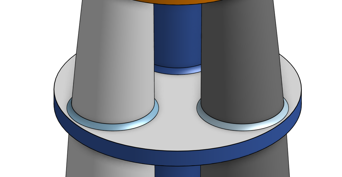
The proposed changes:
With the disks being moved away from the uprights, this would remove that issue anyway so no need for the filleting, the filleting suggestion was to remove this small converging corners.
If the new geometry complies with all of the above then we might have to move on to check things like numerics and the flow itself.
Best,
Darren
Hi everyone,
Good news. I’ve went ahead to re-mesh the geometry. The mesh quality checker has also deemed the mesh OK which is a good step forward. I also went ahead to simulate the new mesh and its still running but is not diverging as you can see here.
I agree with Darren in that additional geometry changes may help the auto mesher to be more cooperative and should be performed for future simulations.
Hope this helps!
Cheers.
Regards,
Barry
The quality of the model is not high, you’re right. I didn’t think this could have been a problem for the meshing system, but it’s my fault. I should have considered also this.
About the last meshing suggestion, everything works fine now and the simulation converges. Thanks to both for the help and the suggestion.
Just one thing. I would like to understand what is the function of the region called inlet. It’ something totally out of my knowledge until now.
Hi @albesaca,
I inserted the region called “inlet” in order to allow better flow development for the atmospheric boundary layer (ABL) inlet that will lead to more accurate results.
The outer cells for the bounding box are relatively large in order to reduce the number of cells of the mesh. If we were to impose your inlet boundary conditions the flow will not be as well represented as it should and may cause result inaccuracies. In order to get a representative inlet without increasing the overall cell count by reducing the individual cell size of the bounding box, the region refinement for the area “inlet” is introduced which I have done.
Hope this helps.
Cheers.
Regards,
Barry