Hi all,
I want to [simulate the impact of two plastic parts]. One hits the other with a speed of 1.4 m/s. The moving part does not rotate. The fixed part should deform as a result of the impact. I’ve modelled the case according to a similar case. However, I get an error during the simulation run: “An error occured while projecting a field because of an empty node list. If you use a contact with an active position tolerance, please check the tolerance value and increase it if necessary to avoid an empty contact definition.” What can I do to solve this problem?
I took a quick look at your analysis and I found a couple of areas I do not quite understand.
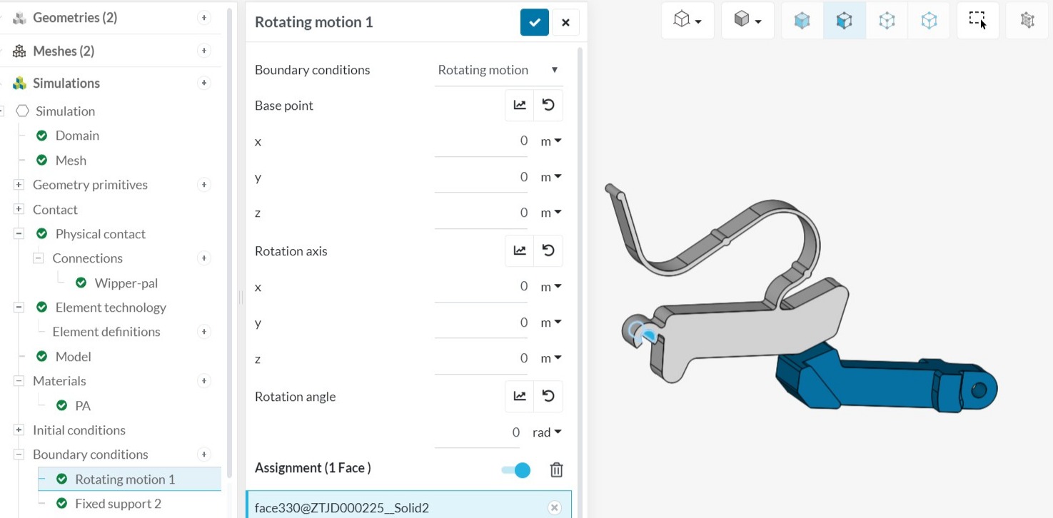
In the image below you have a fixed support defined on the top left of the grey part.
You also have a Rotating Motion defined on the highlighted surface of the grey part. However, this definition is not complete. The Base Point should be at the center of the highlighted surface but point 0,0,0 is off in space. The rotation axis should have the same Y and Z values of the Base Point and the X value will define the vector which rotation is about. Finally, you have not specified an Rotation Angle.
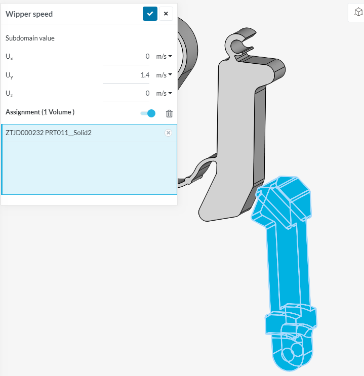
The other issue I see is that the blue part is not constrained and free to move in all directions. Maybe the hole in the part needs to be fixed or something.
Please let me know what you think about these suggestions and let me know if you have anymore questions.
Thank you for your reply. I understand that I did not define the constraints properly. Both parts are in plastic and connected to other parts, not included in this model. The grey part can rotate around the open hole you selected. At the end of it’s tale, where I defined the fixed support, the part is indeed fixed. So, when it rotates around its rotation point, the tale (on top in your image) is compressed and acts like a spring. The blue part moves straight in Y direction towards the gray part. This element does not deform much but makes the grey part rotate.
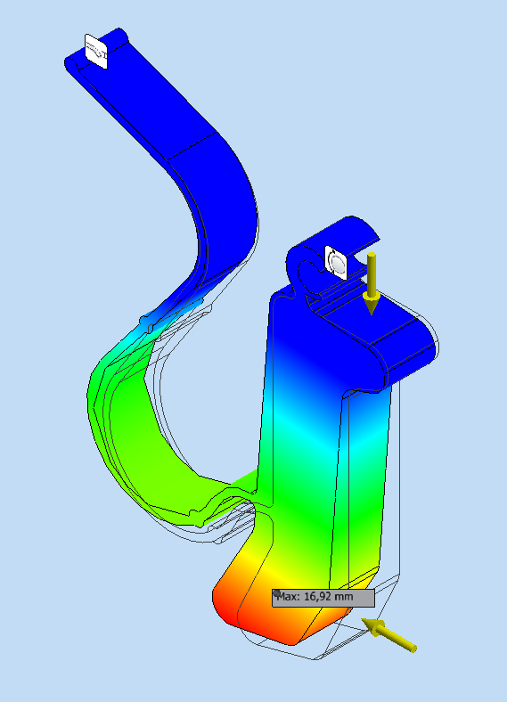
Below a static analysis of deformation as a result of the impact of the blue part.
Does this make it clearer how I aim to define the model?
I set the Numerics and Simulation control after the earlier mentioned project with the impact of a skull with and without a helmet. I just ran a new simulation, but that failed. The error I got is: ‘An error occured while projecting a field because of an empty node list. If you use a contact with an active position tolerance, please check the tolerance value and increase it if necessary to avoid an empty contact definition.’
What am I missing?
Sorry I did not get back to you sooner but work has been very busy.
I have modified your Project HERE. Please take a look at it. It’s not ideal but it does run at this point. I few of the changes I made are:
You had a bonded contact between the two bodies, I removed this.
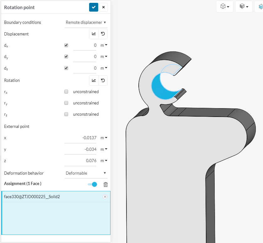
The center of the remote Displacement was not at the center of rotation. Fixed.
The degrees of freedom were not set correctly for the Remote displacement. Fixed.
The modulus of PA seemed low so I increased it to 2.5GPa from .8GPa.
Added damping to material to stabilize the part at impact.
Modified the time step.
Fixed the moving part in X and Z at the pin hole.
Take a look at the project and let me know if you have any questions. I left the initial velocity. This gets the part moving but there is no additional force acting on the part. Because of this the part stops when it contacts. Normally I would use a force or displacement to keep the part moving. but I don’t know your exact boundary conditions.
Please let me know if you need further assistance.