Hello once again,
Im working on a wing for FSAE car, eventually there is going to be a DRS system, so Im trying to achive as much downforce as possible without bothering about drag increasement. It’s my first aerodynamic project so please help me understanding my results. Wing is designed by me, wing profiles I took from MSHD study. Here’s the link: https://www.simscale.com/workbench/?pid=6093534128222503623&mi=run%3A1%2Csimulation%3A7&mt=SIMULATION_RUN
I’ll summarize what Ive already done:
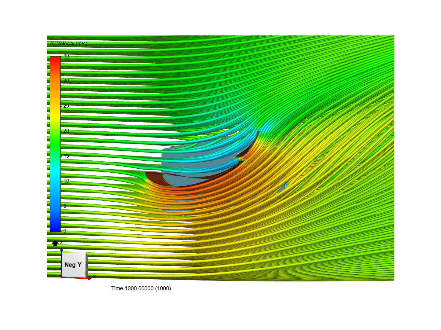
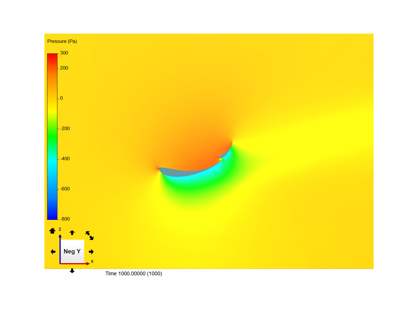
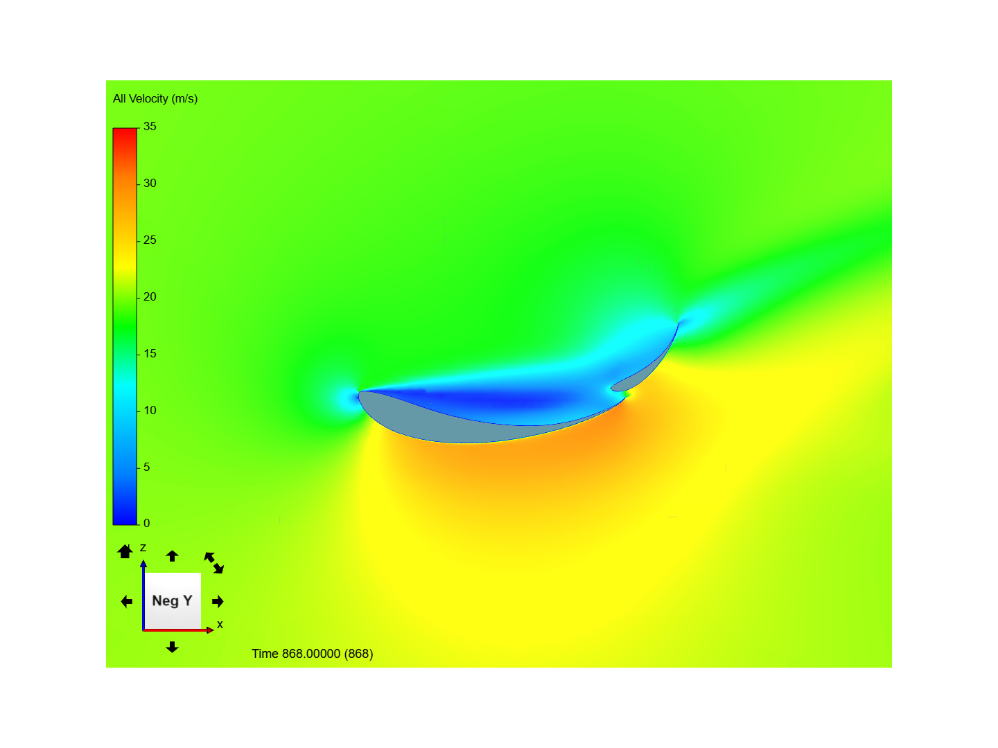
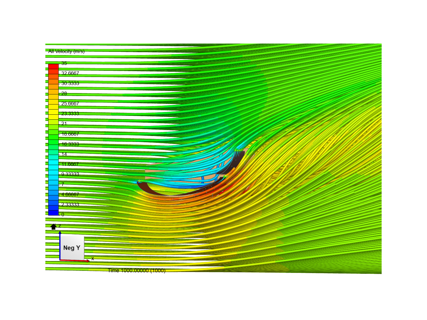
base geometry have been simulated giving aprox. 274 N of downforce and 96 N of drag, here are the velocity and pressure gradients:
I can see big stagnation bubble on the main plate. I think that theres no flow separation on the upper plate meaning that I can increase top AOA. Also I suppose that gap between the plates is too small. Now it is 1,6% of main chord. Main plate is 0 degree and top is 45 ( I have force plots for both of them)
Ive made the gap 3%, it didnt affect the results much, 3N more of Fz and 2 of Fx.
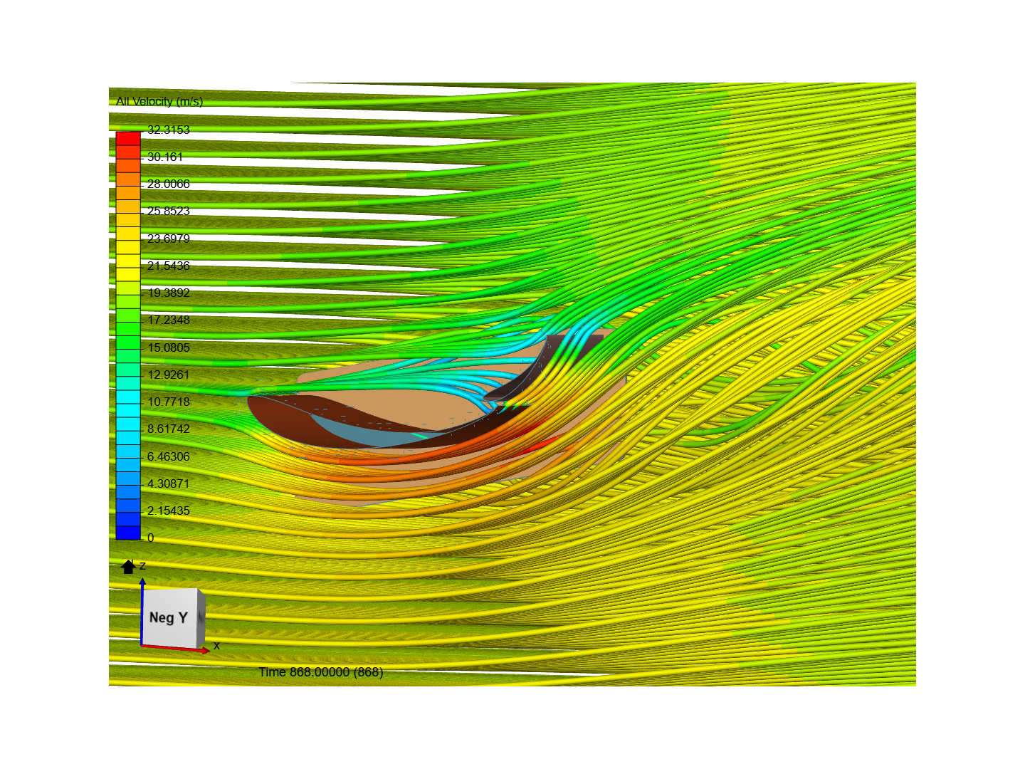
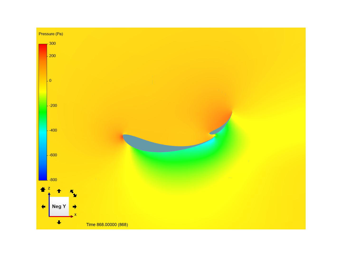
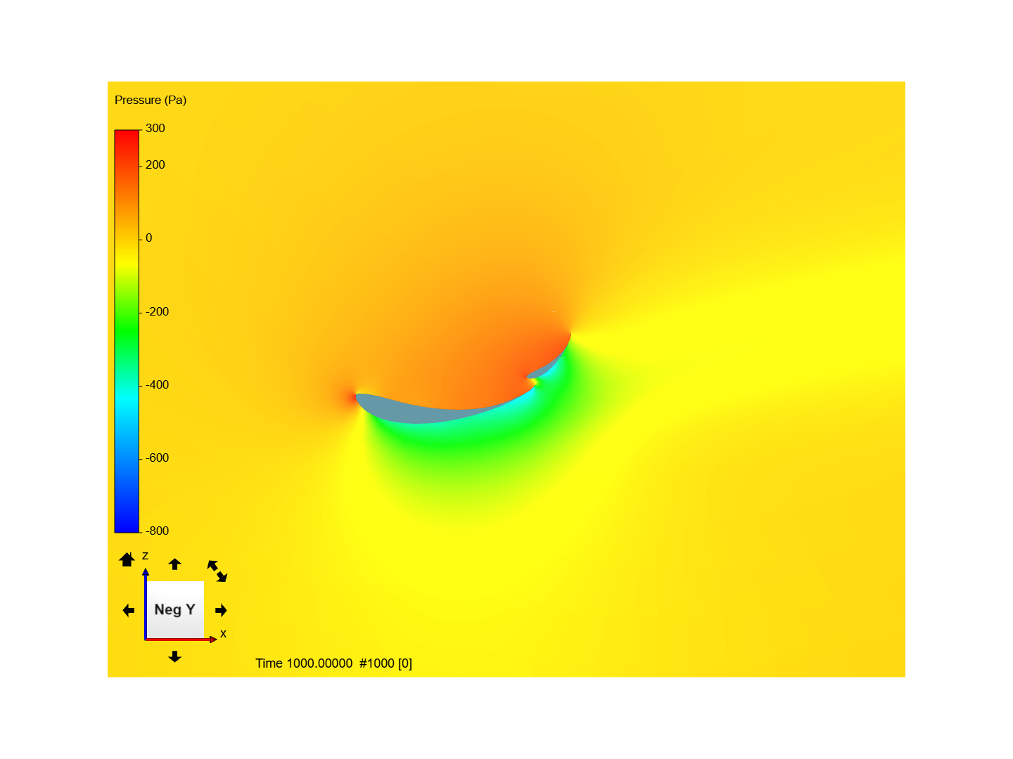
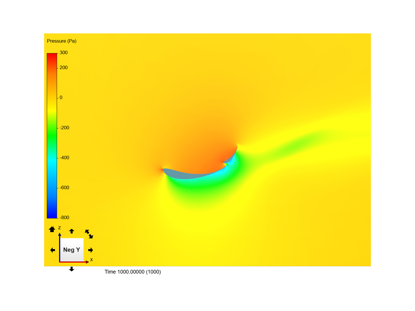
Ive increased main plate AOA by 4 degrees, top stayed the same, gap 3%, after that there were some big changes: 334,5 of Fz and 126,5 of Fx. Here are the screens:
I think that the bigger gap allowed better flow. There’s no such big velocity stagnation. Negative pressure area stays bonded to the top profile higher than before (I suppose its a positive phenomenon). Also pressure on the top side is higher.
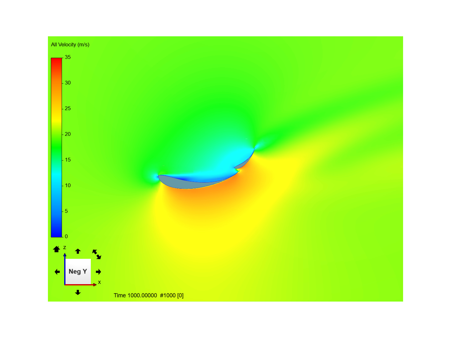
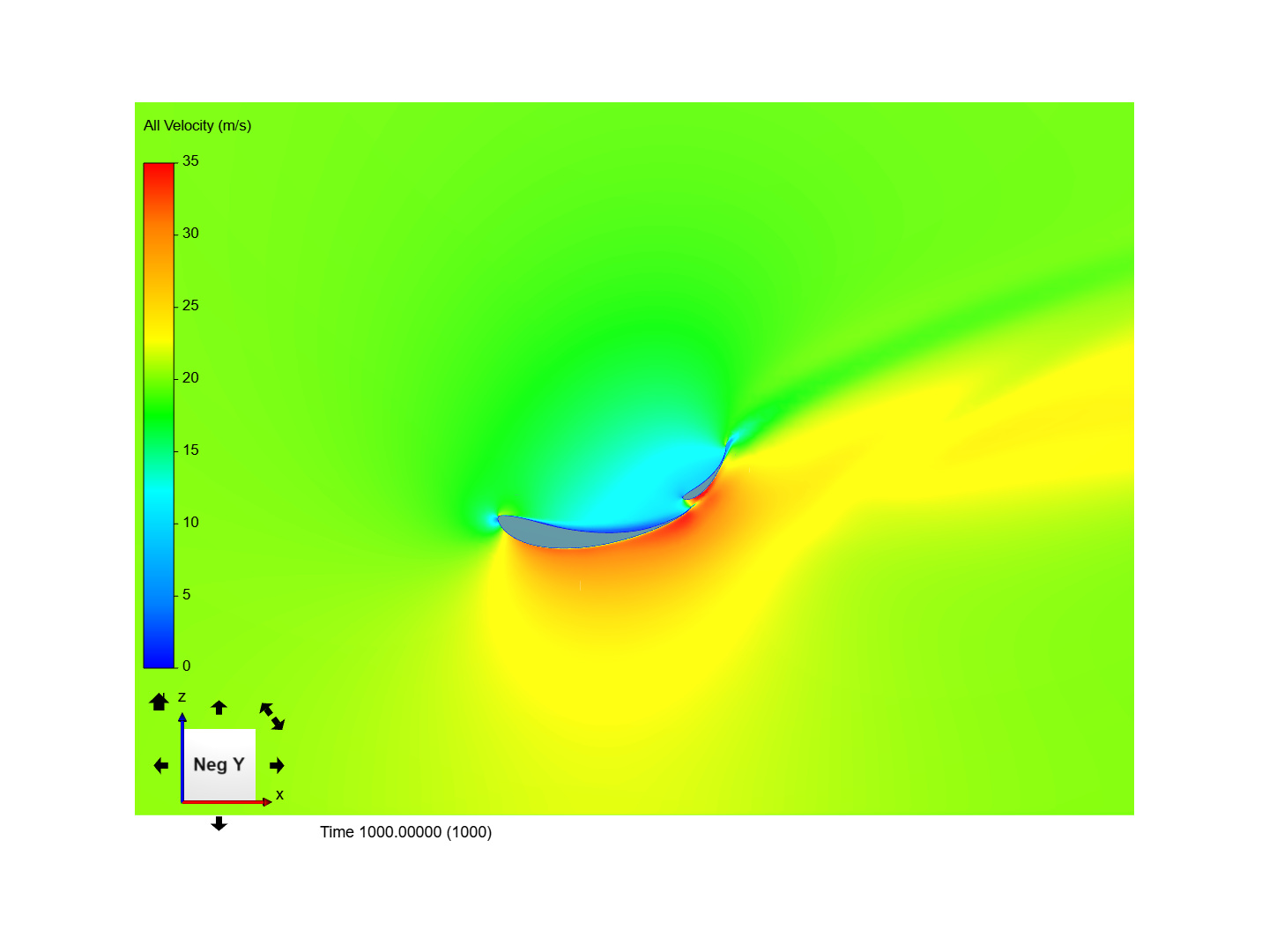
Ive made 3 simulations increasing top plate AOA, 47,49,51 degrees. Forces were gradually rising up to 358 of Fz and 133,2 of Fx.
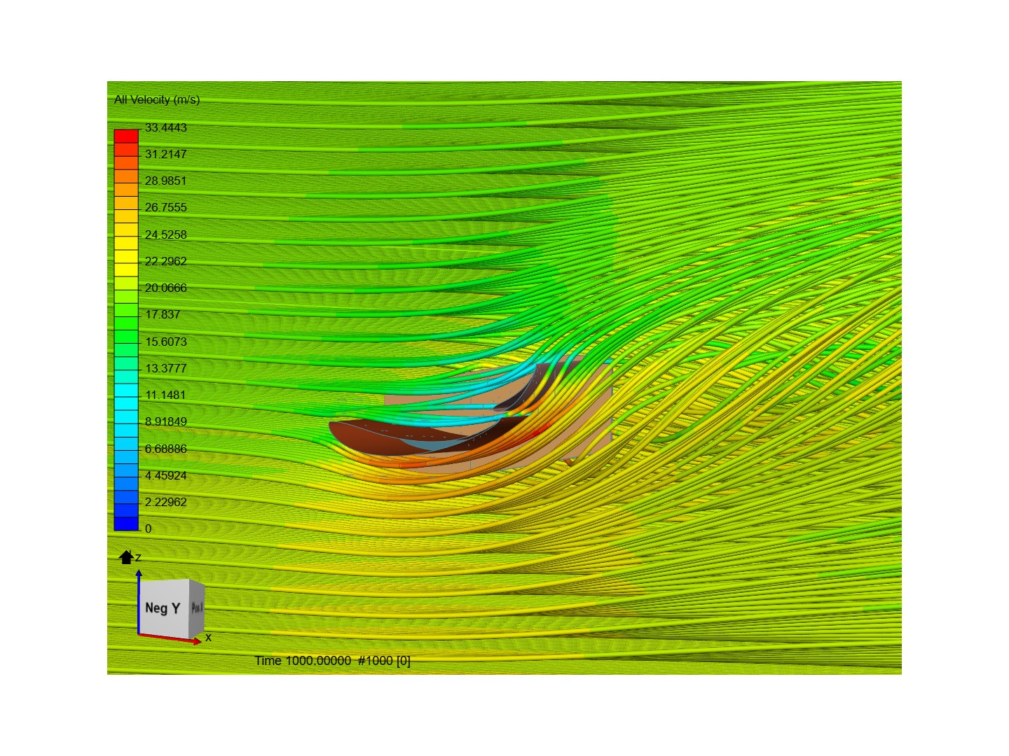
I can see velocity rising on the bottom side and whats connected pressure dropping. I think that low pressure area on the top plate is slight lower than before ( Is it a sign of flow starting to separate?). Particles trace show the flow bounded. My next idea is to make endplates bigger, according to a formula to increase Aspect Ratio. Can you help me analyzing those screen shots and give me some ideas what to change? Sorry for the long post and thank you for your time.
Hello @brumak , try setting an ever more “aggressive” wing by increasing the AoA of the main plate, as you call it. Have you considered going for a 3 element wing instead of 2?
So Ive done endplates enlargement by 20% but it only contributed with 6 N of downforce. Ill give increasing main plate AoA a shot. Can you tell me how do I tell of there’s boundary layer separation? Is the pressure equal to atmospheric in the low pressure region then? And what should I especially focus on?
Flow separation, simply put, is equal to boundary layer separation.
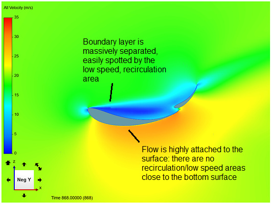
The first image that you posted is a very nice example of both attached BL (bottom part of the airfoil) and HIGHLY separated flow (top part of the airfoil):
If you pay attention, from the 1st to the 3rd simulations, as you changed the AOA, the BL separation diminished quite a bit. I’ve never participated in FSAE competitions so I’m not sure if there is a magic trick that works really well.
Fillia suggested to increase the angle even more. This would help to pressure the BL against the surface, making it less prone to separation. I know that vortex generators are also vastly used to delay/stop BL separation, but I’m not quite sure how easy it would be to implement them.
@Ricardopg explained it perfectly. When you will try to increase the AoA of the main wing, you will notice downforce increase, but also separation on the lower side at some point, so this is where the upper airfoils come to save the day with their duct-like performance, re-energizing the lower pressure side and stopping separation. That is why I earlier suggested more increase in AoA for performance, but also adding another wing for delaying separation while doing that.
I am all for multi element wings, however, it is really important to have a good understanding in why we need them, and why do we place them the way we do. As I said above, having many elements is like breaking down a single big wing to more wings, in order to use the suction and delay separation, so at first I would suggest to:
a) try simulating only the main plate with a chord, as the sum of both your current wings chords,
b) examine at which AoA you will need to “break it down” , then reduce its’ chord approximately before the separation starting point, and add a second wing, and maybe even a third wing.
This will give you a better insight in how the elements of the rear wing work together (and it is a nice process to show to the design judges as well ) Your current design seems to be working just fine, but there is a lot you could try to optimize it by doing the above. Also, you don’t have to use the same airfoil profile for all the wings, remember that the flow from the upper to the lower side has to be smooth.
here’s the result of doubling AoA of the main plate. Both top and bottom boundary layer is not separated and Fz increased by almost 7%. I didnt want to go in 3 or more elements in sake of keeping DRS system as simple as possible.
 ) Your current design seems to be working just fine, but there is a lot you could try to optimize it by doing the above. Also, you don’t have to use the same airfoil profile for all the wings, remember that the flow from the upper to the lower side has to be smooth.