I tried copying the mesh settings from Mesh 1 but that was a disaster because I can not get back to where it was and it wanted me to generate a new mesh
as for now there is no way to remember the old settings. If you are uncertain about future optimizations I would just create a copy of the mesh and work with that.
If I do that, what is the purpose of being able to select different meshes for simulation runs?
Right now, just because I tried the ‘copy mesh settings’ from the same mesh, my whole simulation parameters were lost and a lot of red in a simulation that has many good runs
Those are actually two different topics that came up here. Let me explain:
“Mesh settings have changed” alert box:
As of right now this message is not always accurate. It’s shown even if you only tried to change the name of the mesh once without changing any settings. We’re planning to fix that issue soon(ish).
But @jousefm is right. The best way to preserve old mesh settings is to copy your mesh after it has been generated and to make any modifications only on the copy. This way you have a history of meshes to choose from.
Issue with selecting a different mesh and all assignments being lost.
The possibility to exchange the mesh without losing any assignments in your simulation setup depend on the fact if we can map the entities on your CAD model (solids, faces, edges, nodes) directly (and completely) to your meshes. However, this only works if the geometry and the mesh are sharing identical dimensions, which is not the case for “External” meshing.
But there is a very elegant way to work around that limitation. Check out our Fluid Volume Extraction feature, which let’s you define the fluid domain on the CAD-level already. This way, all your meshes will (most likely) be able to be mapped to your CAD model, making a simple switch of meshes without losing the assignments possible.
Let me know in case you need help or have more questions.
I have found many more issues trying to work with meshes which are sortof embedded into simulation trees and I definitely want to explore Fluid Volume Extraction.
For instance, if I start a new simulation 2 and copy mesh settings from another meshed used in simulation 1 and then change the name of the new mesh in simulation 2 , the mesh name in the old simulation 1 is also changed and all changes I make to the new mesh in simulation 2 parameters automatically change in the simulation 1 tree too. I can not think that this is what is intended…
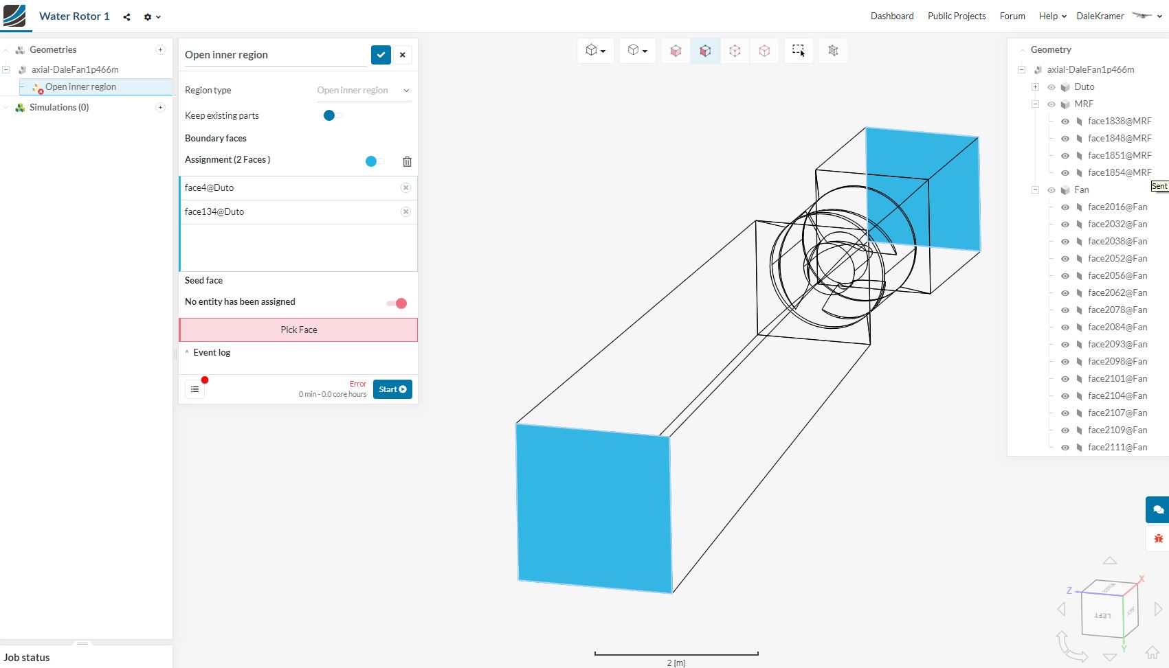
I have tried Fluid Volume Extraction in this project which uses a pretty typical geometry which I can not seem to extract an open inner region from, here is what it looks like. I do not know what face to select as a seed since the inlet and outlet faces do not have a border face around them. :
Before I go back and modify the CAD file to create those borders, is there a way to do it on the existing CAD file?
Why can’t the fluid volume be extracted by using the already existing Geometry Primitive ‘Material Point’, instead of a seed face?
Also, I am very concerned that this CAD file has an MRF as a rotating zone in it (see geometry named MRF) and that MRF will confuse your code that generates the fluid volume… I think you need an ‘Exclusion’ selection frame too
regarding the confusion around meshing:
Meshes are not specific to one simulation, but shared across all of them. That means that making changes in one simulation, will change the mesh everywhere else it is assigned as well. This is intended, but we’re working on a few ideas to make that more obvious in the workbench interface.
In regards to the fluid volume extraction problems:
The case you show above can’t be used for flow volume extraction unfortunately, since you already have an extracted fluid volume. In your case you’d need to perform a boolean operation to cut the rotor out of the fluid domain.
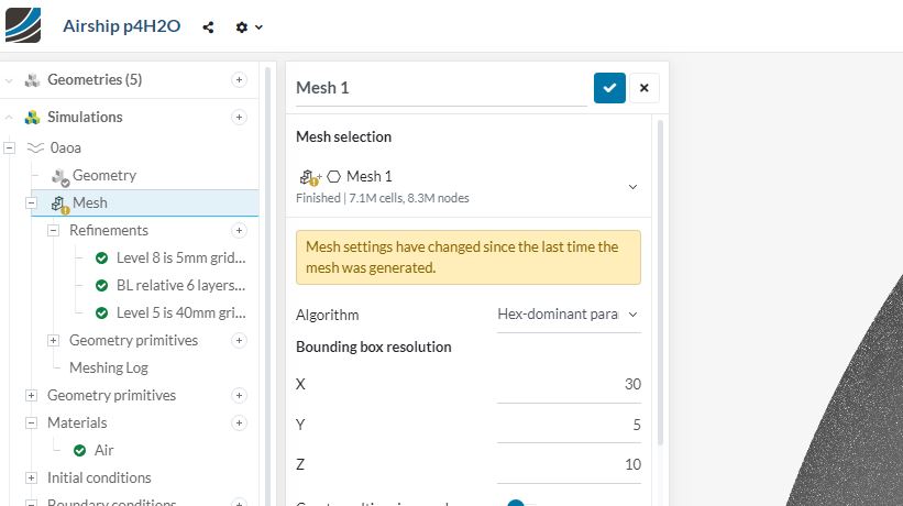
For the flow volume extraction to work for your case, you’d need the walls of the duct as well as the rotor, but still couldn’t keep the MRF zone. Bottom line: Flow volume extraction is not yet optimized for use with rotating zones. But the airship case above would be an ideal use case for it.
I will try to better explain my issue with meshing in another reply after I figure out how to explain it better ( In post #6, I poorly explained my issue)
Is it possible to do the subtraction of the rotor from the walls in CAD and then use that as an ‘open inner region’ for further assignments in SimScale?
Actually, I decided I have too many different project types on the go and I was beginning to ask questions about things that were not related to this main topic issue.
In the meantime Bryce has created a topic on Fluid Volume Extractions and I want to see where that goes.
I think I will leave this topic relatively untouched and summarize that the ability to Reset meshing to where they were when a mesh was created does NOT exist.
Which is too bad because this is sorely needed…
A small step towards that end, Sebastian stated:
AND, I just tried to see if this single issue about renaming a mesh was fixed yet, but it is not
So, watch for new topics after I do some more testing
 and a lot of red in a simulation that has many good runs