How to mesh Conjugate Heat Transfer when there is no 3D model for the air

Hello,
I’m trying to test how to make a thermal simulation of an electronic system with air flowing over it from a fan.
I saw some webinars but in all of them there was a 3D model of the air.
I saw some examples where the air was formed by a geometry primitive and a 3D model, but the result was only the air mesh without the 3D body’s mesh.

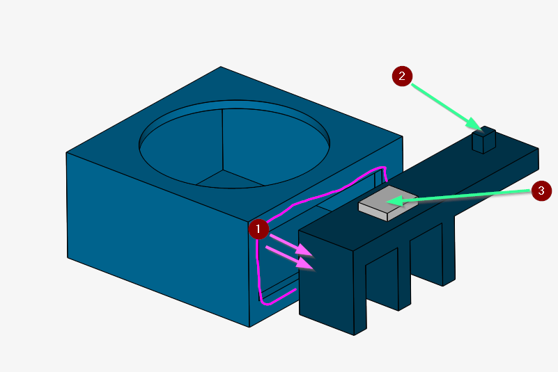
I wish to simulate a fan pushing 0.5m/s of air from opening (1)
The face (2) generates 5W and the LED (3) generates 15W.
In my CAD I don’t know how to create a 3D model of all the air around the solids.

I’ve created a Hex-dominant mesh for the geometry (internal).
After the mesh was done I made the background mesh box larger in order to simulate the air around the parts, and made a Hex-dominant mesh (external) for it.

I add a new Conjugate Heat Transfer Analysis
If I select the geometry or the internal mesh as a domain I can:

  • Add solids materials.
  • Add absolute power source of 15W to the LED-A (3).
  • I’m not sure if using the wall boundary is the way to set the 5W on face (2)?
  • Add thermal connection between the hot plate and the led.
  • I cannot assign the fluids materials!
    If I select the external mash as the domain I can:
  • Select air for the fluid material.
  • I have no idea how to define the 0.5m/s air out of the fan as there is no surface there.
    if I add a surface to my 3D model will it transform into simscale?
    should I add a thin body at the exit surface of the fan?
  • I cannot define any of the things I did when the domain was the geometry.

So, my questions are:

  1. Is there a good tutorial that can help me?
  2. How can I get a mesh with both the air and the solids?
  3. What should I do to define the air from the fan?
  4. How to set the 5W from surface (2)?

Thanks,
Momo

1 Like

Hi Momo!

Thanks for the detailed post! Would a convective heat transfer analysis not be more appropriate for this application? I assume you are not cooling your device with water but want to perform active/passive cooling simulations, is that correct?

If so then your model has to be closed anyway and the parts have to be connected or touch the box with which you close the ensemble of parts.

Conjugate Heat Transfer (CHT) needs touching surfaces! You can see that by inspecting the meshing log if the master & slave faces have been detected. A good guide can be found here: CHT - Electronics Cooling


Let me know how you want to proceed with your setup so that we can go a step further and improve the geometry.

Cheers!

Jousef

Jousef,

I did read the guide you linked before I started my test.

Yes, I use a fan and air to actively cool my device. My real design has a plastic case so most of the heat need to be taken actively by the air.

Convective heat transfer is read: “when temperature changes in the fluid lead to density variations and movement of the fluid due to gravity.” In my setup the air temp should not rise more than 70C so I don’t believe that there will be big density variations.

In that guide there is a 3D model of the air. I’m not sure how can I make that with my CAD system, and I hooped that it will be easy to create in SimScale.

I first wanted to see the fan effect when there is no case, and only then add the case.

And yes, I would be very happy go get more help on this! :slight_smile:

I found a very fast and easy way to create the air body in my CAD!
So now I mesh has both the air and the solids.

I still don’t know how to:
3. How to define the air from the fan (there is no surface there) ?
4. How to set the 5W from surface (2)?

Hi Momo and sorry for the delayed response, was a bit busy :slight_smile:

So referring to your last post you managed to enclose your geometry, did you use the enclosure tool from SimScale?

Regarding the two remaining questions:

  1. I personally would invest some more time into the pre-processing and add the surfaces manually as you have seen in the template I provided you with. Proper geometry is let’s say 80% of the work :smiley:

  2. If you can find a formula to calculate the temperature for a 5W component including thermal resistances (if that even goes into the formula like for LEDs) you can use the temperature in the CHT analysis and work with that. Afaik there is no way at the moment to explicitly say “Please 5W here and there”.


Let me know if you have any further questions.

Jousef

Jousef,

I wanted to use SimScale for the enclosure, but could not find how to make a mesh of both the air and the solids.

I did found how to model the air in my CAD, so after importing that file to SimScale it’s easy to mash all the solids (and the air is one of them).

But I still have a problem with the definition of the surface from which the air gets out of the fan.

If I model the air as one solid (“fan_test_with_air_and_solids”) there is no surface in the air body at the outlet of the fan. So I cannot select it in boundary conditions step.
I even added a surface at the fan outlet to my CAD model, but it was not exported/imported into SimScale.

To overcome this I did a second CAD model, in that model I made two air solids. One a small box placed at the fan outlet (“air out from fan”), and the other is all the rest of the air body. (“Conjugate heat transfer + air body+air out of fan” simulation).

I imported and meshed this, but could not set it to run:

  1. “CHT + air body+air out of fan 1” simulation-
    I set all the materials connections and heat at the LED.
    I added air velocity at the exit of the fan outlet
    Then made a run, but it ended with an error. The event log only says “Job was prepared successfully.” Which does not help :frowning:
    I tried to switch to transient mode to see some output but this also failed to run.

  2. “CHT + air body+air out of fan 2” simulation-
    I had the feeling that I need to connect the two air bodies, so air can flow from one to the other.
    The only way I could think how to do so was using the connections (“air out” “air in”) but I’m not sure that “no-slip” + “Coupled interface thermal” is the way to do so.
    When I try to run this, I get an error “Multiple boundary condition or interface assignments for the following entities: face35@air out from fan-A”
    “Face35@air out from fan” is the face with the velocity outlet condition.
    So this way also don’t work…

I really need an hint no how to simulate a fan flow placed at the middle of the air body.

Momo

Hi Momo,

I think what you are looking for is something like this (see at 1:18):


The problem is that nothing of your components is enclosed so what seed face do you want to pick? At least in my point of view there’s no way in achieving this with a geometry setup like this. So as mentioned beforehand, you have to do it manually and close also the face where your air comes through and close the rest as well.

I think what you want is a setup that looks like this: Printed Circuit Board Cooling with Conjugate Heat Transfer by Ali_Arafat | SimScale - where the components actually touch the ground. I doubt that you have that big of a domain around your components, right?

Please let me know if that helped.

Jousef

Hi Jousef,

In short:

Your replay helped me to understand how to make the air body.

But I keep getting “Simulation run failed” no mater what I try to tweak in the settings, and the event log is always “Job was prepared successfully.”.

The long story:

The video was very helpful. I completely missed the option of adding the air enclose from the Geometries -> add geometry operation. This command removes the need to model the air in the CAD program.

I also found in the video the option to select “assign other” and select the faces behind the cursor (I kept looking for that…)

The lack of encloser in my geometry was not a problem. I used the enclosure command and set the XYZ min/max size and got the air body (did that on “fan_test” geometry).

My original idea was to start with a simple simulation without a case and only later add it.

As you asked about it, I added another geometry “fan test with case”. You can see that the in vents are far from the fan actual inlet.

I would like to use the simulation to find from where the fan actually get its air, so this is why I wish to assign the velocity to the fan outlet (in the middle of the flow region) and not to the box inlets. But I’m still not at that step as I cannot get the simulation to run :frowning:

What ever simulation I try to run I keep getting the error:

The following simulation run(s) failed:

  • Run 1
    Please check the ‘Event Log’ and ‘Solver log’ for more details.
    In case of questions, feel free to contact us at support@simscale.com or ask in the Forum.

But the “Event log” is always “Job was prepared successfully.” And there is no entry for the “solver log”

This dos not help me in any way to find the problem in the model.

For example, you can look at my last test “CHT with case, parametric mesh”.

This has the geometry with “add geometry -> open inner regions”, a hex-dominant parametric mesh with “create multi region” on.

The simulation only has the fluids and solids set to air and aluminum.

I added only velocity inlet on two faces of the air, and pressure outlet on some near faces.

Set the simulation control for a very fast run.

And still with only this simple set up I get that unhelping “Simulation run failed” error message.

What do I miss?

Hi Momo,

let me have a look at your case tomorrow - hope you’re not in rush. I assume that something with the master-slave surfaces might wrong or just a BC issue. Will let you know as soon as I know more :slight_smile:

Thanks for your detailed description of your problem by the way. Cheers!

Jousef

I took some hours to make more tests on the problem of failed run:

I started with a simple geometry and added more and more solids. For each geometry I did the same mesh and same simulation settings.

Test_model1+2+5 worked and finished the simulation.

Test_model3+4 failed to run.

From this I can conclude that the problem is with “fan body” but I have no idea why.

I’m running out of battery, will keep testing tomorrow

===================
Did more tests:
The system probably have some problem with the part “fan body”.

In simulation “CHT_test my model 4, none laminar” I tested all the none laminar solvers on a model4 (case + fan body). all failed.

In simulation “CHT_test mo model 6, new fan body” I replaced “fan body” with a new part with the same concept of inlet from top and exit to the right. this one did run.

so:
a) the error log just don’t help to understand to source of the problem (as it say totally nothing)
b) I have no idea whats wrong with “fan body”.
c) If I wish to continue with model 6, I have the value of the air flow from the fan outlet. putting that value in the outlet of the case is totally wrong. I need to be able to define the air flow from the outlet surface of “fan body2” (the circular face). Can I define this in SimScale?

thanks,
Momo

Will get back to you soon Momo,

will check this out. I assume there’s still an issue with the geometry. Please also check your inbox.

Best,

Jousef

@momo62,

regarding your simulation settings you have chosen the analysis to be transient but I think steady- state should be fine considering the huge amount of resources that will be consumed.

In addition to that if the steady-state simulation fails you can use the interface option to “map” faces together that have not been detected as overlapping from the mesher. Try steady-state first and let me know how things go, we will make this work :slight_smile:


Cheers,

Jousef

Jousef,

Actually all these simulations are set as “steady- state”.

It was confusing to me to see that I select Time dependency = “steady state” when I add the simulation, but still in the simulation control I can select the “Start time”, “End time” etc.

I tried to find some info about this “map” faces together” in the forum. I found some interesting stuff but not that.

On my fail run (“CHT_test my model 3_failed!!!”) there is no data under the simulation runs, only the settings.

I did try to import the X_T file back to my CAD and could not find any problem there.

Hi Momo,

I’ve checked the settings and numerics and the simulation itself are set to steady-state - currently trying to run the simulation with the “test_model6,_new_fan-A” mesh and see if I can make it work.

Regarding the time step settings the names are just random variable names and you can leave the time step to 1. If you use the steady-state time discretization just leave the time step as 1 which is one iteration if you like. Your outputs are not time steps, they’re just named that way. Keeping you up-to-date!


Cheers,

Jousef

Hi Momo,

finally some progress from my side :smiley: The thing is that some surfaces where not properly detected due to the mesh and you also did not add a part that needs to be cooled which does make much sense for this type of simulation otherwise we could just have used an incompressible simulation type. In the picture below you can see the added Power Source with 20W (just for testing purposes) and changed the boundary conditions as you can see in the tree. Worked like a charm!

If you want you can try it out by yourself and let me know if you have any problems with the setup.


Best,

Jousef

Jousef,

I did not added the heat in the last run just in order to make it easy to compare my different tests.
not sure how you solved the “some surfaces where not properly detected due to the mesh” did you re-meshed it?
can you share me your copy of the project?
is it possible to set the air velocity at the exit of the fan case?

Hi Momo,

we can try the outlet of the fan case. What I would suggest (would have to test if it works though) is to add a momentum source as a substitute for the fan. Otherwise you would have to provide a detailed geometry which we neglect by just adding this source so would not have to add additional modeling details to your components.

For the meshing I simply switched from very coarse to coarse to make sure the surfaces get detected properly. Will share the project with you in a minute.


Cheers,

Jousef