I want to start out by saying I’m an absolute beginner, but I have done the tutorials related to my task at hand.
I want to model a couple nozzles with compressible flow. However, I am having trouble getting the simulation to accept that there are multiple faces, and where the inlet vs outlet will be once I mesh it. That is, when I go to assign an inlet or an outlet, the entire object is selected.
I went to use a tutorial model for meshing practice, and saw that it worked fine, which didn’t help me figure out what was wrong with my actual CAD design. Furthermore, once I went to run a simulation on the tutorial model, it returned an error stating that it “encountered an error that could not be resolved by adjusting the outlet values”. I did select both an inlet and outlet, however.
I’m modeling using fusion360 and importing as an STL, if that’s important.
Greetings,
I also use fusion360 to create geometries, Usually I save models as a .step file and it’s been working great for the most part.
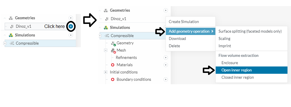
As for your problem, before you’re able to select inlets and outlets, you have to extract the flow volume (basically you’re telling the software what is fluid and what is solid). To do this, you have to go here:
From these 3 flow volume extraction, you will have to pick the one that fits your geometry. If you need further information, here it goes:
How to Create Flow Volume Extraction? | Knowledge Base | SimScale
Once you run the flow extraction, you should be able to select specific faces within the flow region.
/Ric
4 Likes
Hi @johnmichaelh24,
Can you share the project link with us, it will help us understand what wrong in your simulation setup.
Regards
1 Like
Yes, here is the link to the tutorial that’s giving me errors: [Tutorial - Automated Hex-dominant for internal flow by johnmichaelh24 | SimScale]
and here is the link to my model that is automatically selecting the entire object:
1 Like
Hey,
I see you have a lot of things going on! I’ll try and go through some points from these 2 links that stick out:
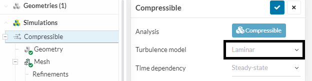
First link: - The turbulence model you’re using is laminar but you’re working with air at 350 m/s. Choosing turbulent would be appropriate here:
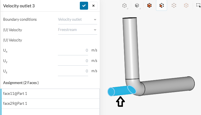
- About the boundary conditions, commonly (but not always) they’re set as some sort combination of velocity inlet (could be speed, mass or flow flux) and pressure outlets. You’ve set velocity inlet and outlet conditions.
This is what is causing your simulation to crash. The error that the software is returning is “The continuity error cannot be removed by adjusting the outflow. Please check the velocity boundary conditions.” Try changing the outlet BC to pressure outlet and see how it goes.
Also, I think you selected one outlet face by accident:
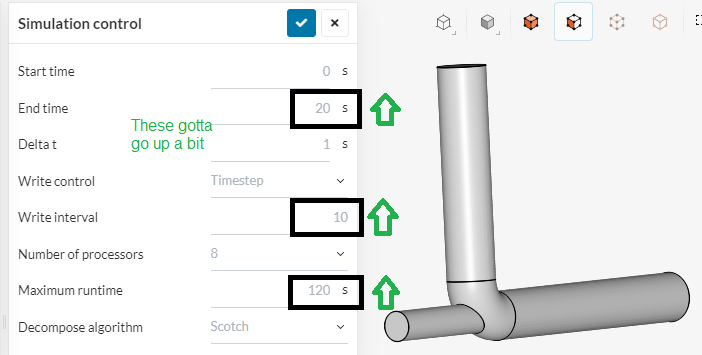
- Lastly, your simulation time is pretty small, you’re running only 20 iterations. This will definitely not be enough to allow the simulation to converge. Try setting it to 300 or 500 as a first guess:
Now the second link:
- So first off, there could’ve been an unit error when you were working on this geometry. The nozzle seems to have 100 meters diameter. Was it intended?
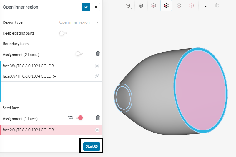
- You cannot select inlet and outlet faces because currently there’s no flow region in your simulation domain. For this specific case, you will have to run an open inner region operation. Try following these steps:
Run the surface splitting. Then run an open inner region:
Select both boundary faces on the first box and one seed face in contact on the second box.
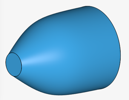
And this is the result:
There you go, you should be able to select inlets/outlets now.
/Ric
3 Likes