Dynamic CAD base model for Simscale CFD
The basis of this project is to find a way to efficiently change the dynamic driving conditions of a FSAE racecar in Solidworks in preparation for CFD simulations. The goal is to have the ability to change Pitch, Yaw, Roll, and steering input angles easily in the base model so that different simulation situations can be done quickly. Normally these changes are very difficult unless mechanical mates are made to all suspension and steering components.
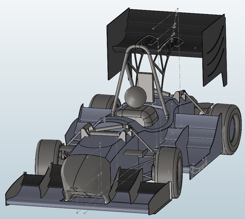
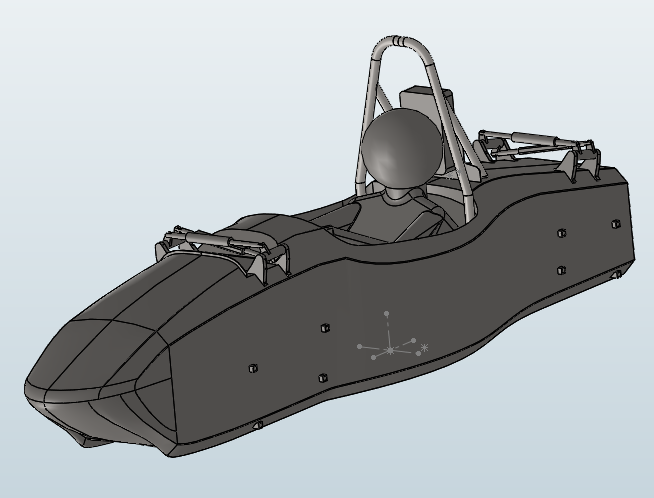
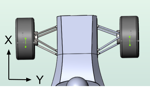
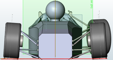
The 2019 CFD simulations were done using a specific roll, and steering angle to simulate a specific turn radius at a specific speed. This limited the ability to develop the aero package under different driving conditions. Improvements would certainly have been made if there was the ability to design the aero under braking, turn in, and accelerating conditions. Shown below is the model used for the 2019 cornering simulations.
The first main problem with this project is setting up the mechanical mates correctly. Solidworks can be very problematic when mates are made incorrectly or even in the wrong order. I hope to find a way to show how this can be done so that there are no errors when moving the model to different positions. Starting with the suspension, I will document the different methods attempted and the solutions to achieve the results needed.
1. Mono and bracket setup
It is important as the first step to have both the mono and suspension system to be sharing the same mating planes. This will make connections later in the project much simpler. Either set these up from the start or have one bracket or part have the master planes.
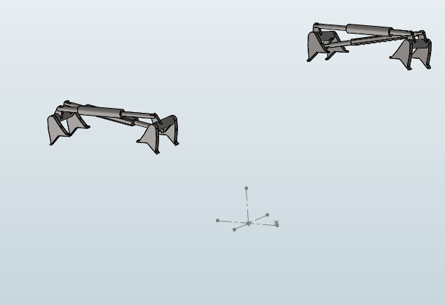
The first step is to connect the suspension mounting brackets to the mono. However, since these will not be moving components, simple mates can be used to set these pieces into position. Using the mono as the base part of the assembly file, add all brackets or mounting points until every part touching the mono is in the right position.
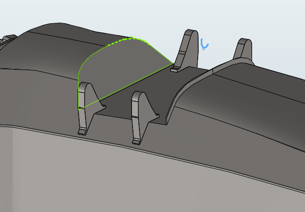
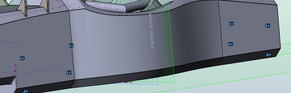
Making solid connections to complex geometry can be done using a simple method. All brackets are cut or mated short of the mono (about 2mm works fine). Then a sketch on the bottom face is made, the profile copied, then extruded to the mono as an external reference.

Once all brackets are mated correctly, it is easier to save them as one part file so they can later be selected in the CFD program. To do this, simply delete the mono in the assembly file, then save (as a copy) the collective bracket setup as a (only for this case ) new assembly file.
Now there is a separate assembly file with the correct positioning and mating planes to quickly attach to the mono later. The suspension system can also be built directly in the original assembly file but I prefer these two to be seperate for now. This will allow for easier updates if any changes to the suspension parts needs to be done.
Now the other non-moving parts of the suspension can be added.
When designing this assembly for CFD it is important to group as many individual parts together as possible. Unfortunately, at the moment, Simscale no longer supports a single STL file as a single selection in the tree pane. Earlier, when this feature was available, this reduced the amount of parts that need to be selected.
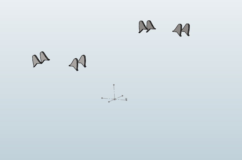
Next, all ball and socket mounting points that I have attached to the car was positioned using the same method as the suspension mounting brackets, then a mirror was made for the other side. All mounts were saved as a single part file which is best done at the same time as the suspension brackets. However, saving this as a different file and then inserting into the suspension bracket assembly can add flexibility later if things need to be changed.
Saved as Part file by deleting everything in the assembly then saving as a copy - sldprt file.
This ball and socket part file was then added to the suspension assembly file.
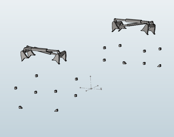
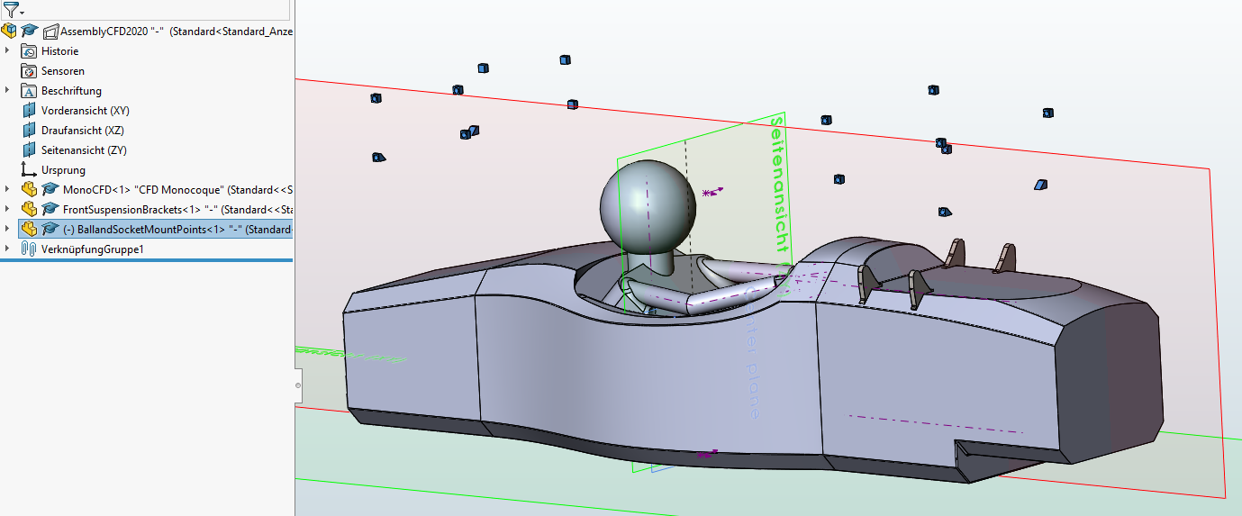
Then the main hoop and head rest were added as the final suspension assembly. Now all the small geometry parts that require a higher mesh surface refinement are grouped together.
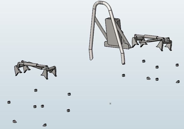
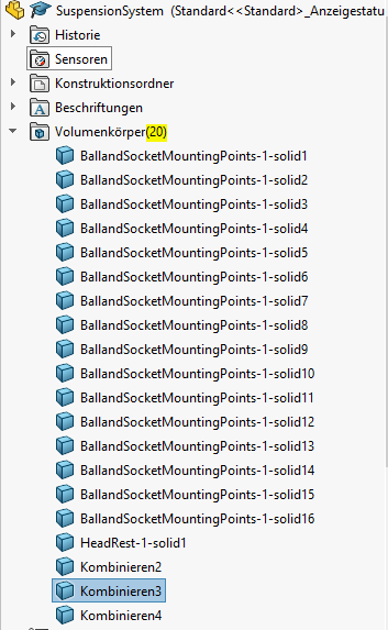
At this point, with the new Simscale setup, every solid body in the part or assembly file is able to be selected individually. For our goal this is a disadvantage as the grouped suspension could have been just a single selection. However, in order to reduce the amount of selections, and therefore potential errors, the combine function can be used in solidworks. Notice how there are only 20 solid bodies in this part file. The combine feature can unfortunately only be used for bodies that are physically touching each other, otherwise the whole part could have been one solid and therefore one selection in Simscale.
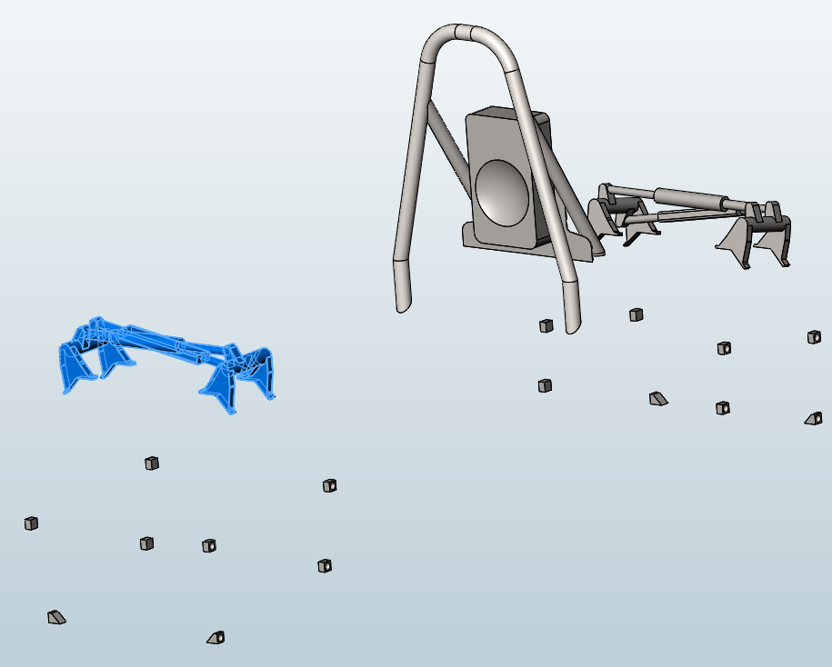
This assembly file is now saved as the final Master Suspension Part file and reinserted into the mono and suspension assembly.
2. A-arm setup
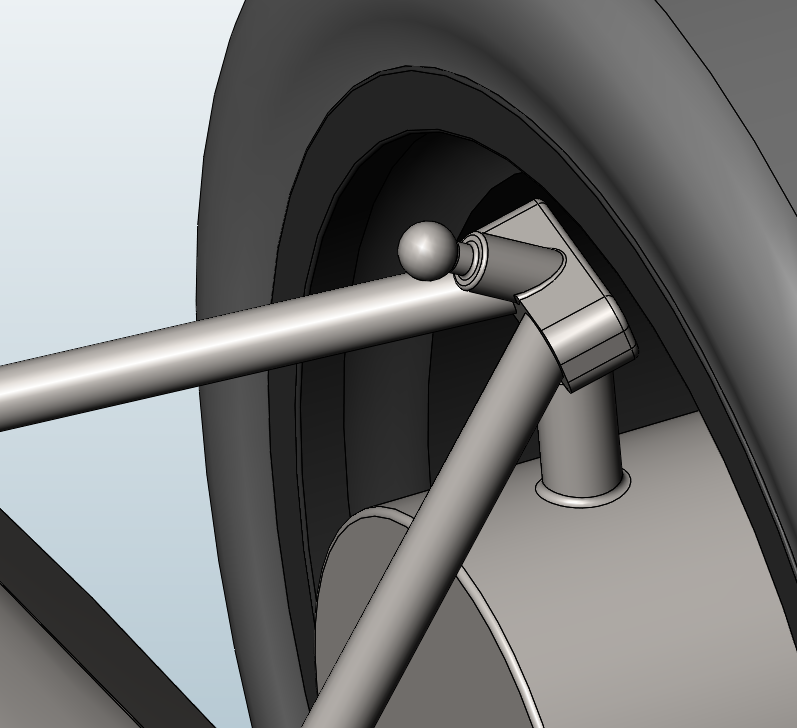
The first attempt to create the dynamic A-arm suspension system ended with a ball and socket design on the motor and two concentric mates attaching the A-arm to the ball and socket bracket. This did not work however because the A-arm length must be exactly correct for the concentric mates of both arms to work.
Instead the solution is to mate the wheel assembly (shown later) and move everything as close as possible to the correct location then to create one part by using the combine features. A simpler method is to simply delete everything in the assembly except the A-arm, then save the file as a COPY and as a PART file. Then delete and replace the original uncombined part with the new saved one.
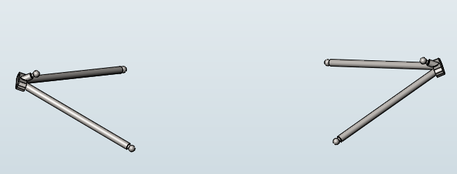
The new coupling method worked in creating one part out of the two A-arms and ball and socket joint. However the geometry with so many linkages was unnecessary and a simpler solution was made. - Shown right
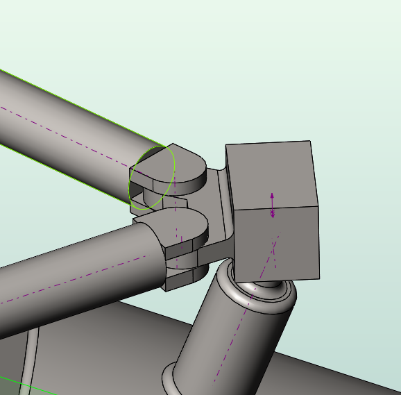
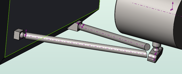
After some trial and error in what mates will accomplish the correct suspension movement. It was found that concentric mates between the motor and A-arm, and ball socket mounts an A-arm was allowed. (shown below)
Creating the A-arms will now be shown.
After the first upper A-arm was set into place. The lower can now be created. Both arms must be saved as separate part files otherwise changes in length to one arm will affect the other. It is important to constrain the wheel to its original location to ensure the correct distance. The position of the ball and socket mounting point to the motor is unimportant, however it must not contact the wheels during turning or load changes. Creating the full A-arm requires simply editing each Arm and extending it to the body of the mounting bracket.
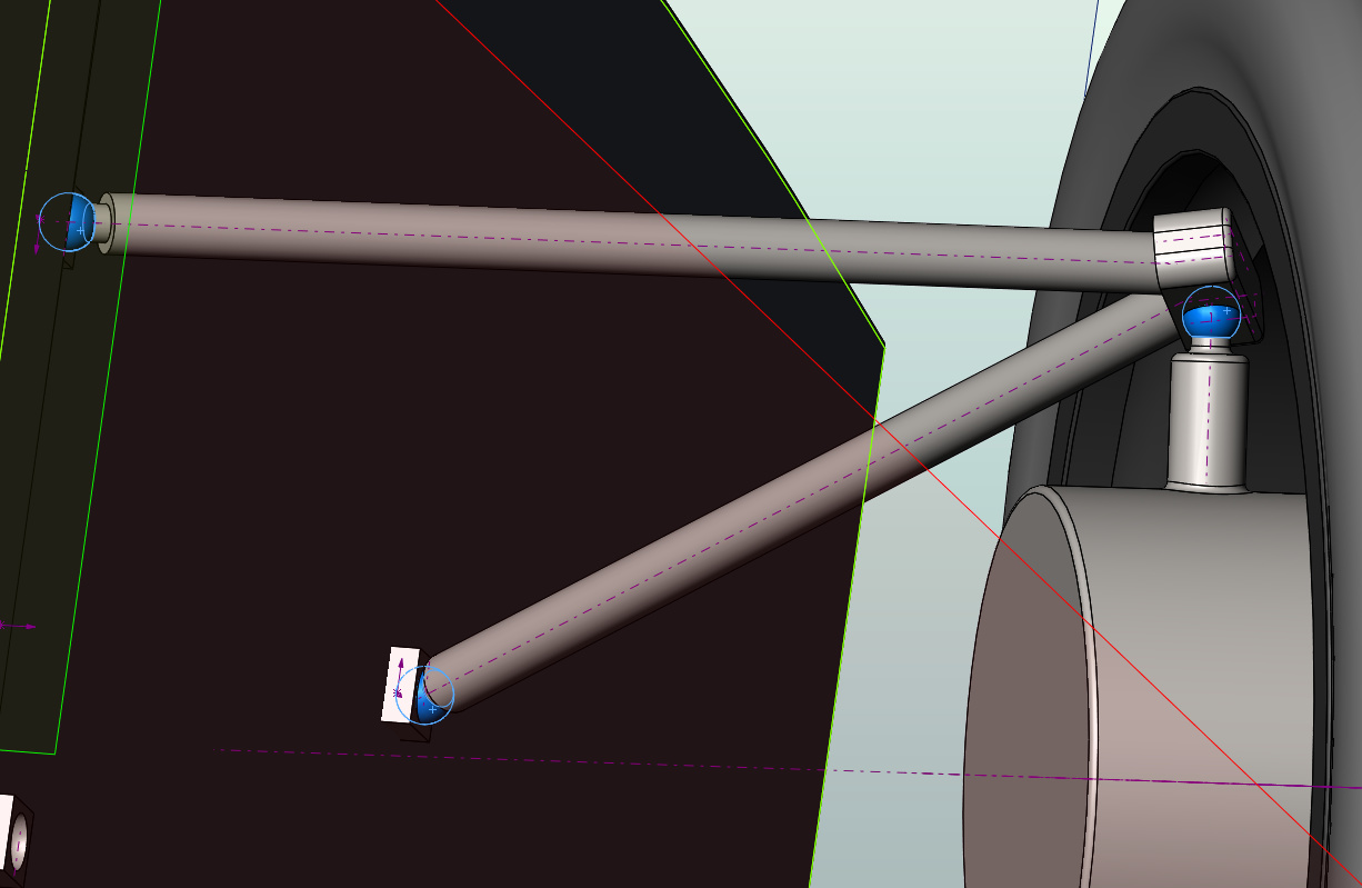
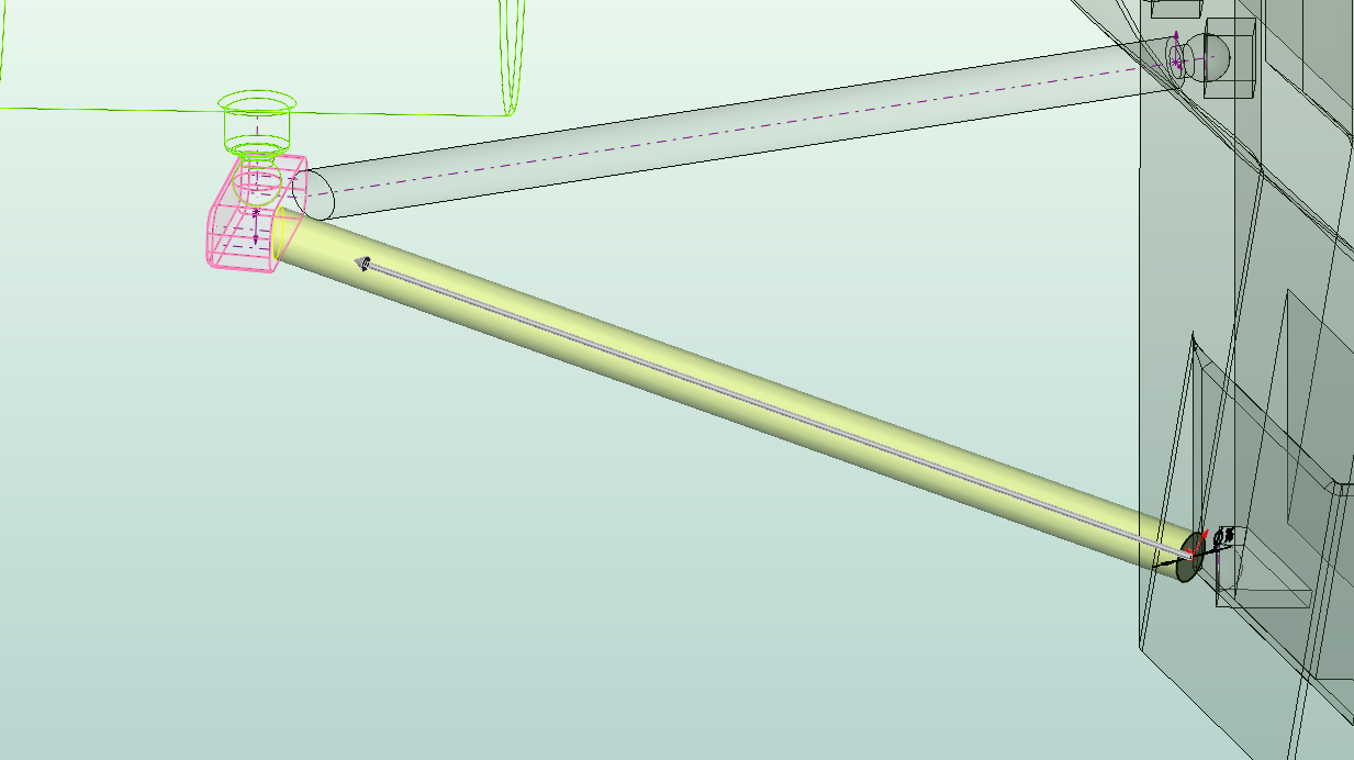
My method is inserting a blank part file into the assembly, then creating a 3d sketch to use as the reference line from the ball and socket mount to the motor mount ball joint. Then with the desired radius a extend to body feature is used and the motor ball joint mount is selected (pink).
By repeating this process, an exact A-arm can be constructed. Then, as shown before. Delete everything in the assembly, and save as a copied part file.
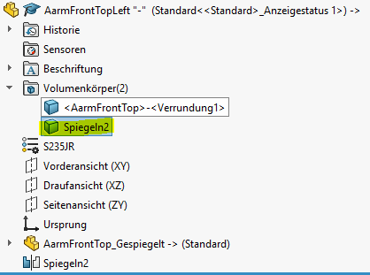
It is also necessary to create both left and right A-arm sets for the mono. Mirroring these parts can be done but certain steps are required so that changes to the original A-arm are not translated to the mirrored part.
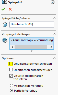
First mirror the part in the part file, with the solid body merge function unchecked
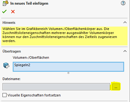
Then open the solid body folder and right click on the new mirrored part. An option will be “Insert into new part” then select the three search dots and input a new name. Then click the green check button.
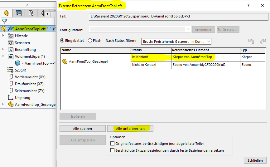
The new part is now created, however, the features from the original are still connected to the mirrored part. To break the link, right click on the part file, select External References. Shown below is the part in context to the original part file. Select the break all button at the bottom of the window. The mirrored part is now free of its connection and can be used.
All completed A-arms can now be inserted into the master assembly file, however it is better to first setup the wheel assemblies in the master file first as shown below.
3. Master Assembly File Preparation
IMPORTANT
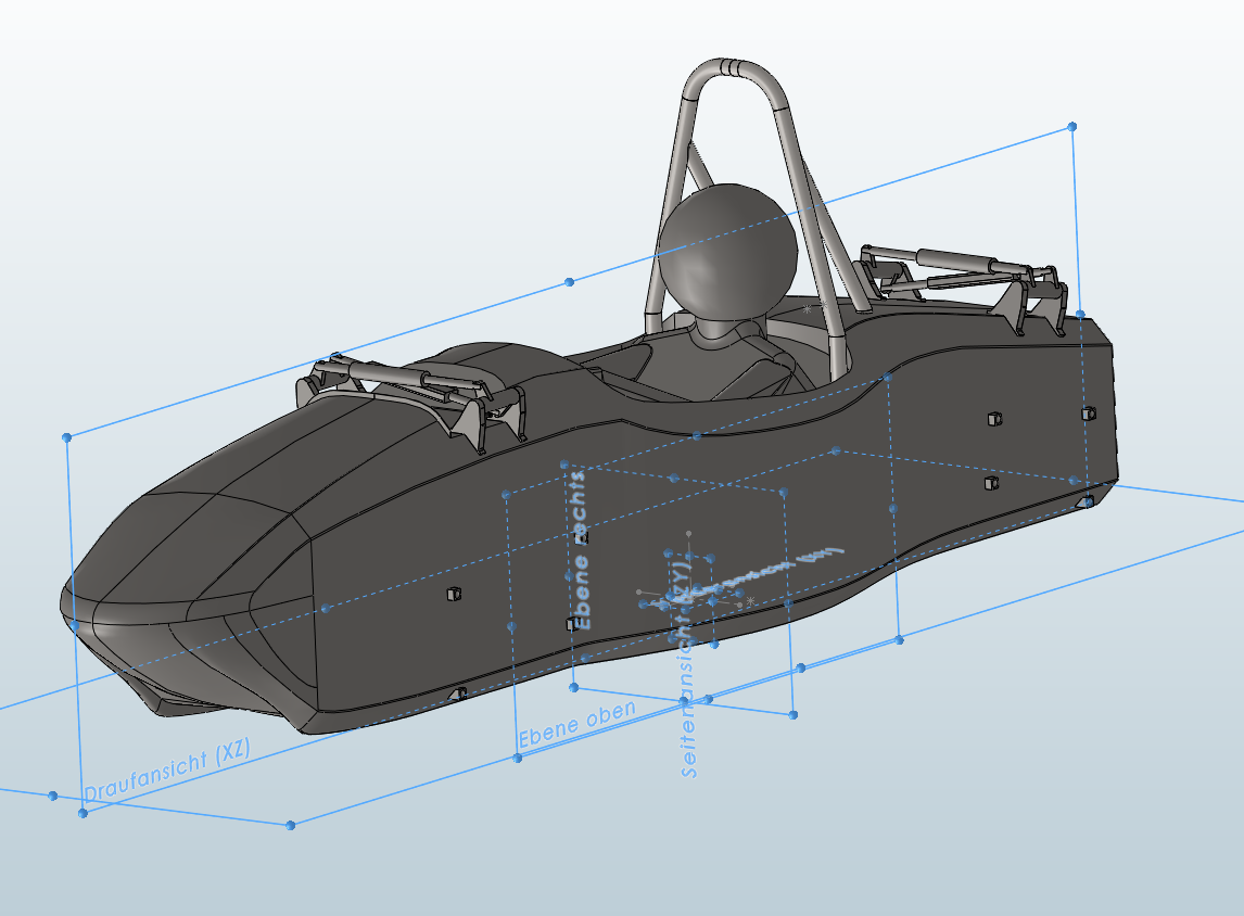
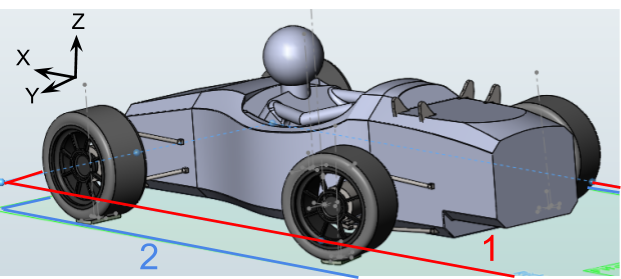
The orientation of the car in this model, as well as its origin point will be transferred into Simscale when the STL is uploaded. Therefore, for our car, and easier calculations later on, the origin of the master file should be located at the center of gravity, which is exactly centered between the wheelbase. It is also located on the X axis traveling in the -X direction so that Inlet Velocity and other inputs can be made positive.
The master file was setup by using a ground plane with a construction sketch on it. This sketch has the wheelbase and track width of the car which has the center point of the where each tire meets the ground. Sketches at each wheel point are made parallel to the cars direction of travel.
Vertical planes were also created on either side of the car running through the centerline of the wheels. On each plane connected to the wheel centerpoint a vertical construction line was made.
4. Wheel Assembly and positioning set up
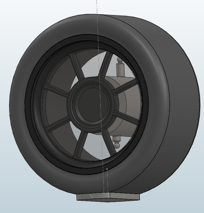
Moving on to assembling the wheels. Create a new assembly file and insert your wheel file, motor, contact patch and MRF zone. It is easier to mate everything in the context of the assembly file planes. The MRF zone is shown as transparent here.
The front wheels provide the most difficulty as they must rotate on their vertical axis in order to turn. To make this setup less difficult and to have less chance of mating errors, camber, toe, and caster angles will be left out. To accomplish a turning wheel at the right position. The mates must be done to the final master assembly and not the monocoque as the wheels will move later. The X and Y positions must be mated to the origin of the wheel. Mating to planes will restrict movement. The Z mate can be between planes.
Important Simulation Pre-information
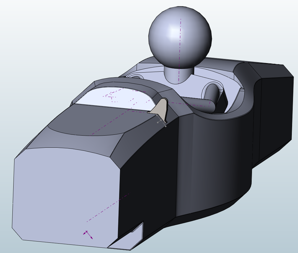
Normally, a 5mm contact patch is cut into the tire where it meets the ground. This is done so that the mesh can be generated correctly as direct contact between the tire and floor results in an incredibly small angle and more illegal faces. This is shown below compared to with the contact patch.
For this assembly, all contact patches were extended to 15mm so that with induced camber of the wheels, the patches would still extend to the floor. The area that goes through the floor will not be a problem because during the simulation, only what is inside the simulated wind tunnel will be affected. A plane at the 5mm mark was created, along with X and Y direction sketches for future use.

Moving on to the assembly of the rear axle, many different mates were used to find how the chassis would still be allowed to move with the constrained wheels. The first attempt mated both rear wheels along the X,Y, and Z axis so that only the mono was free to move. This however let to over constraining the mono. Further attempts included wheel sketch to assembly sketch mates, wheel sketch to plane mates, and wheel plane to assembly plane mates.
When the final mates for the mono itself were created to control the pitch, roll, ride height and yaw, these mates once again over constrained the assembly. This first Trial will be left in the report even though they are wrong to show how the thought process and to help explain why these mates will not work. The solution in the second trail changed the mates again to allow for maximum freedom of the car while still keeping accurate settings.
After many failed attempts, the final solution was a combination of the following mates,
Trial 1 (Unsuccessful method - Front and rear axles)
Rear Wheel Mates
- This is a parallel mate done between a sketch that is 5mm under the contact patch part (at the actual meeting point of the wheel and ground) #1 and a sketch in the master assembly file that is located in the center of the wheel on the ground plane #2.
This mate locks in the vertical Z movement as well as the movement along the Y axis however lets the wheel rotate about the X axis, (camber adjustment)
-
To locate the car along the X axis, the center point of the sketch #1 was selected and mated to a plane along the rear axle 2 of the car in the assembly sketch.
-
To keep the tire on the ground the same point 1 is mated to the ground plane 2
-
Lastly comes the limit angle mate. This is used to limit the camber allowed when the chassis is moved but does not fix the tire to a specific angle. This is done by mating a fixed vertical axis sketch in the assembly file with the vertical axis sketch at the center of the tire.
-
This last mate is only necessary on one side of the rear axle as it restricts the movement of the entire assembly from moving along the Y axis.
Now the same steps must be repeated for the other side with the exception of step 5 and the rear tire movements will be set. Now time for the front.
Front axle setup
For the front wheels an extra challenge is encountered because they need to be able to simulate turning. Complexity is added when the axis of rotation 1 is not on the same plane as the wheel center 2. This is shown in the picture below.
Upon closer inspection, the problem lies with the fact that as the wheel angle increases 1, the pivot point 2 moves the center of the wheel 3 off of the X axis by a certain distance 4. Therefore mates considered between the center of the wheel and the X axis were found to over constrain the model.

After much trial and error it turned out that minimal, non-constrictive mates were needed for the correct function.
- First a mate between the center of the wheel and the ground plane. This positions the wheel on the ground Selecting a point for the front wheel mate, unlike a line used for the rear wheels, allows the tire to still freely rotate.
- Another limit angle mate, just like what was done to the rear wheel. This is done by mating a fixed vertical axis sketch in the assembly file 2 with the vertical axis sketch at the center of the tire 1. Repeat steps 1 & 2 on the other side.
To position the wheels into the correct steering angles, an angle mate must be created between a sketch on the ground plane along the X axis and an axis running through the tire 1. As of now this is the only way to change the steering angles without disturbing the other mates. I would have preferred one master sketch to change all needed angles but this is too complicated for such a dynamic model.
5. Trial 2 (Successful method - Front and Rear Axles)
After the adjustment settings for the mono were created at the end, it was discovered that constraining the wheels to the master assembly model cause more problems. Below are the correct mates that led to a successful dynamic model.
Rear Axle
-
Just as in the first trial, the centerpoint of the sketch cutting through the contact patch (the actual bottom of the tire) #1 is connected to the ground plane #2.
-
To limit the movement in the Y direction, the same centerpoint of the contact patch #1 is mated to a vertical (Z axis) plane (right plane) #2 that runs as the theoretical plane between the rear right and front right tires. This will pin the right rear tire to this spot but still allows the rest of the car to translate across the ground plane. This freedom of movement will be important later.
-
To locate the car along the X axis, the center point of the contact patch sketch #1 was selected and mated to a Y directional sketch on the ground plane along the rear axle #2. This mate is more effective if it is done on the left rear tire because it helps limit the movement of the car.
- The final step for the rear axle is a parallel mate between the X directional sketches located in the contact patch plane. This locks both from rotating like the front tires.
These are the only four mates used for the rear axle.
Front Axle
-
Just as in the rear axle, the centerpoint of the sketch cutting through the contact patch (the actual bottom of the tire) #1 is connected to the ground plane #2.
-
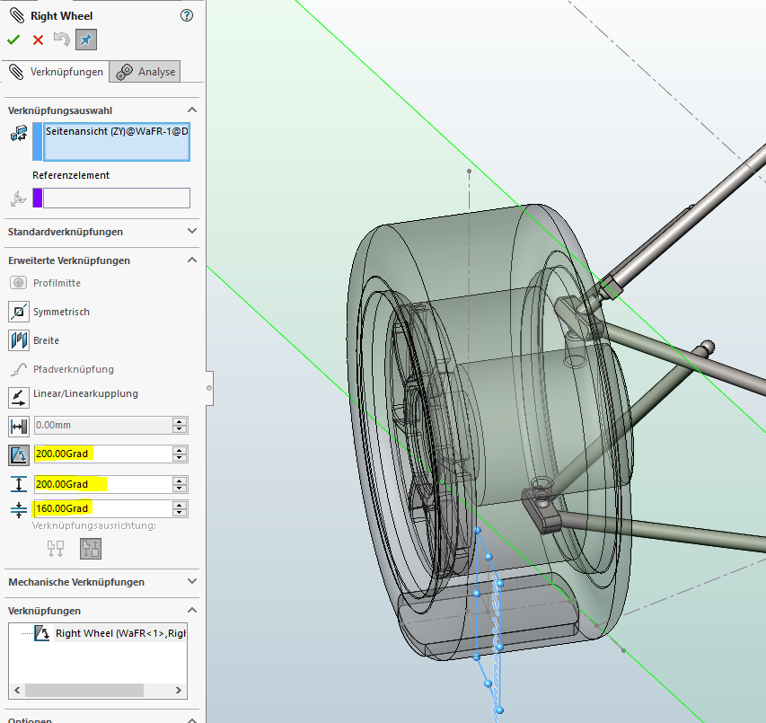
For each front tire an angle mate is created from the vertical center plane of the tire #2 and the center plane of the mono #1 … NOT the master assembly center plane as this will over constrain the assembly and the wheel angle must be relative to the mono, not the master file.
These are the only two mates for the front axle.
For the angle limit mate, it is better to set the 0 deg mark at 180 deg because solidworks cannot handle a model that is moving through the 0-360 deg mark. For example: Setting at 0 deg will lead to the wheel moving to a negative angle or through the 0-360 deg mark. Therefore it is better to have a range of 160 to 200 deg.
Once the wheel assemblies are inserted into the master file, the A-arms should be added next. Making concentric mates at the motor to arm ball and socket connection. After that add in the mono and suspension assembly file.
6. Mono angle settings
The last task for this dynamic model is to be able to change the heights and angles of the mono. The process to find the correct mates was very time consuming but the mates are not overconstrained and all needed adjustability requirements are met.
- The first task is to create a 3D sketch that is made by editing the mono part file itself. This is not done in the assembly. It must be directly attached to the mono. Also a centerpoint was added at the intersection of these sketch lines.
Next, a series of planes must be created within the master assembly file to allow for movement of the mono angles. These planes must be built upon each other so that the relations between them are kept. It is very important that this structure is built correctly so more description will be added.
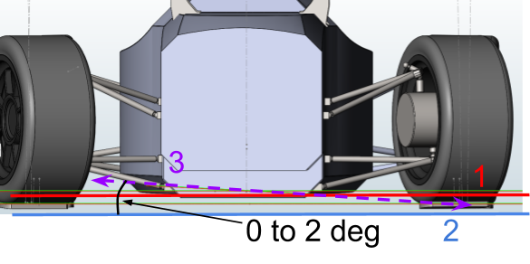
- Every angle setting, Pitch, Roll, and Yaw must be able to be changed while the ride height remains unchanged. Therefore, the first step is to create a plane that simulates where the bottom of the mono is. This plane is made in the master assembly file. Set a random distance from the ground plane #2 to the plane that would be the bottom of the mono (ride height plane) #1. I chose the lowest FSAE ride height at 35mm for now.
Now, built off of this “ride height plane” will be the pitch and roll planes. This is done so that any change to ride height will automatically move the other planes with it, allowing for an unconstrained model.
-
On the ride height plane #1, create a sketch that runs along the X direction #3.
-
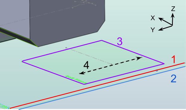
Now create a new plane by first selecting the “ride height plane” #1 and then the sketch that was just created #2. Then set an angle relation. This can be set to 0 deg for now to avoid trouble later. This will give you control of the cars roll.
The result should be a plane, attached to the “ride height plane” that has a roll angle. To test that everything is working, change the angle of the roll angle plane, then change the distance between the ride height plane #1 and the ground plane #2.
- The same kind of thinking will be applied again but now creating a pitch plane. Same procedure as before but now the sketch will be done in the newly created Roll Plane #3. Create a sketch on the roll plane along the Y direction #4
- Again create a new plane by first selecting the “Roll Plane” #3 and then the sketch that was just created #4. Then set an angle relation. This can be set to 0 deg for now to avoid trouble later. This will give you control of the cars pitch.
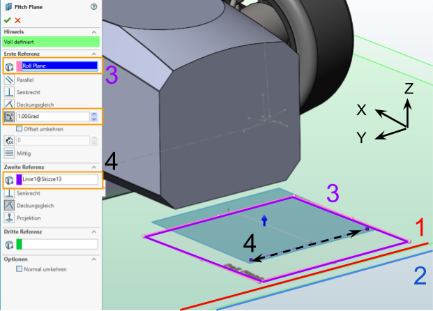
- Now a pitch plane has been created #4. Again testing this can be done by moving the roll angle plane and checking that the pitch plane moves with it.
-
Creating mates to these planes can now be done. Start with a coincident mate with the center point of the 3D sketch made in the mono part file #2 to the “ride height plane” #1. This allows the ride height to be changed by moving the distance of this plane. It will also move the Roll and Pitch planes with it allowing for these angles to be kept.
-
Next use a parallel mate between the Roll Plane #1 and the sketch line running along the Y direction found in the 3D mono sketch #2.
-
Another parallel mate is made between the Pitch Plane #1 and the sketch line running along the X direction found in the 3D mono sketch #2.
-
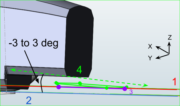
The very last mate controls the Yaw angle of the car. Since the previous three mates take up a considerable amount of free movement of the car a fully constrained Yaw angle mate would over constrain the model. To avoid this an angle limit mate is created. This can be done between many different sketches but I chose the X directional sketch of the rear wheels contact patch #1 mated to another X directional sketch on the ground plane in the master assembly file#2.
Conclusion
The result is not perfect but it works. When changing the angles of Roll, Pitch, or Ride Height, the model needs space to move otherwise it becomes too over constrained. By using a limit angle mate the “stress” of these changes is translated into Yaw angle movement or wheel angle. This is allowed because the front wheels are not constrained to the Y axis and therefore allows the mono and wheels to move together. Attempts to limit the Yaw angle movement to 1 deg in each direction resulted again in an over constrained model. Therefore a limit of 3 deg in each direction was used and allowed for the correct movement. This angle can be edited after all the other angles are set so that the correct Yaw angle can again be used.
7. Solutions to over constraints when moving the model
- Sometimes dragging the model a little is necessary to remove the over constrained model. This is especially true when the wheels are pointed straight ahead at 180 deg.
- Moving the whole model (Yaw angle change) can be beneficial
- Suppressing some of the mates until the model is almost in the correct position (suppressing ride height mate works well, so does the Yaw or wheel angle limit mates).
- Over constrained wheels that will not return straight ahead to exactly 180 deg can be solved by first setting the yaw angle to 180deg, then fixing the mono in place, then setting the wheels to 180 deg, and finally un-fixing the mono.
Im sure i have missed something or made a mistake somewhere so feel free to contact me if you have any questions. Just send me a PM on Simscale or if I dont respond within a couple days (because im not always active) my email is ds4719@att.net
I will also try to upload this model to grabcad after i talk with my team captain for approval.
 We can couple it with some CFD animation, let me know what you think.