
I am a high school student working on a CFD research project involving a small seaplane UAV hull. I am using SimScale’s transient multiphase VOF solver with air and water.
The hull essentially behaves as a planing hull, and I am currently testing it at:
- Velocity: 10 m/s
- Pitch/trim: 0°
- Air + water: VOF multiphase
- Gravity: -9.81 m/s²
- Stationary hull with prescribed incoming flow
- Transient simulation using the OpenFOAM-based multiphase solver
My goal is to compare different hull geometries, including a biomimetic geometry, based on their hydrodynamic performance and spray generation.
I would like to extract quantitative values for:
- Hydrodynamic drag
- Hydrodynamic lift
- Pitching moment
- Wetted surface area
- Maximum spray height
- Potentially a quantitative measure of the overall spray envelope/spray volume
I understand that SimScale has force and moment calculations, but I am unsure about the best way to configure them for a transient VOF planing-hull simulation.
For example:
- Should hydrodynamic drag be obtained directly from the integrated force on the hull’s no-slip surface?
- Should I separate pressure and viscous contributions?
- Is the force reported by SimScale already accounting for the air/water density variation through the VOF phase fraction?
- Should I normalize the force using a reference area to obtain (C_D) and (C_L), and if so, what reference area would generally be appropriate for a small planing hull?
- Should the force values be time-averaged after the initial transient reaches a quasi-steady state?
- Is there a recommended way to extract the wetted surface area of the hull as the waterline moves dynamically?
The spray measurement is where I am especially uncertain.
I would like to quantify something such as the maximum vertical spray height above the undisturbed free surface. I am currently visualizing the VOF interface using an approximately (\alpha=0.5) phase-fraction isosurface.
Would measuring the maximum Z-coordinate of the (\alpha=0.5) surface be a reasonable way to define spray height, or would that be a poor metric because individual droplets/spray structures may not have (\alpha=0.5) cells?
If there is a better way to quantify spray height, spray envelope, or spray volume from SimScale’s available post-processing tools, I would really appreciate guidance.
I am ultimately trying to establish a repeatable methodology where I can run several hull geometries under identical conditions and compare their drag, lift, pitching moment, wetted area, and spray characteristics.
Any advice on how an experienced CFD user would set up the force calculations and define/measure spray metrics for this type of VOF planing-hull problem would be greatly appreciated.
Current problem:
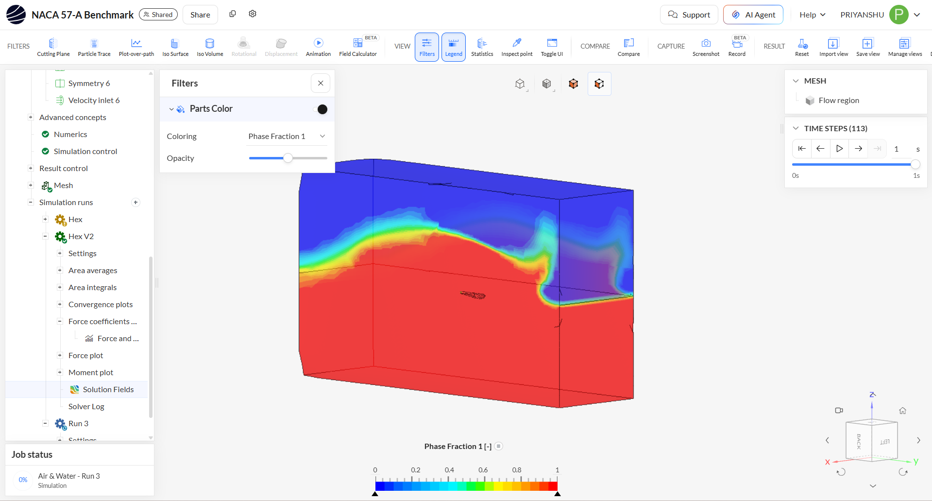
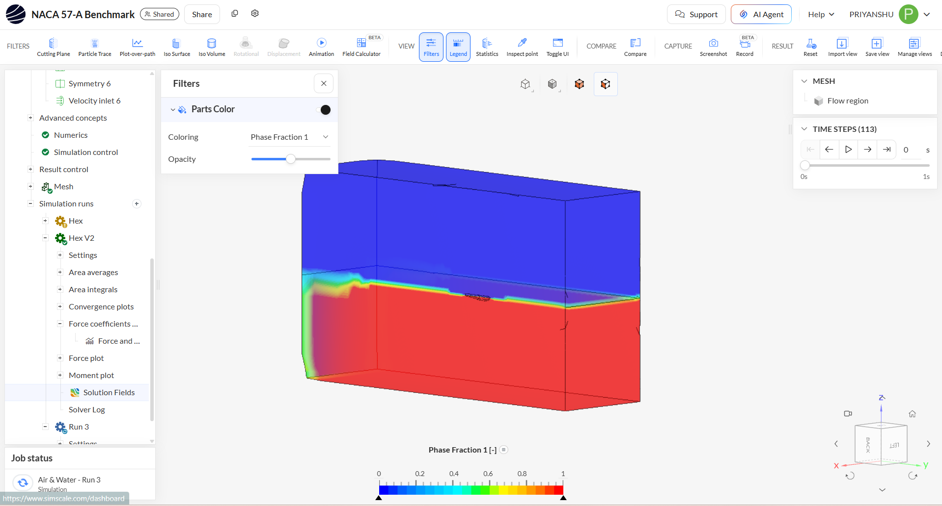
I created a multiphase simulation with an external flow volume. Within the simulation I created a geometric primitive cartesian box for the water domain and set it to phase value of 1 in initial conditions phase fraction subdomain. For my BCs, I created two separate velocity inlets with one having a phase fraction value of zero and the other having value of one. The issue is that it immediately creates a tsunami-like wave starting from the first time step. I have attached images. My initial solution was making the global velocity 10 m/s as well and it does not create the tsunami, but I am not sure if that is the correct way to solve this issue.
Thank you!