It seems that in my simulation setup is some kind of error, because the velocity is higher than initiated. For example I have a velocity of 5.4 m/s initiated, but in simulation “30deg final” the velocity is far higher than that, leading to faulty results of the measured forces.
I did not have much time to check it out but, your simulation is blowing up (diverging).
After a quick look, I noticed that for, some cases, you used slip walls. However, in the last one you used a pressure inlet-outlet boundary condition (check out this post: Pressure Inlet and Outlet | Boundary Conditions | SimScale). The way in you set-up this BC was a zeroGradient condition for the pressure and velocity and a wall function for the turbulent quantities, which does not make much sense. Try setting up a freeStream configuration, which works much better for external aerodynamics.
In addition, you have set an initial internal field value for Ux=0 , which again, makes no sense. It should be set to the same value of the inlet boundary. Also, do use a potential flow initialization.
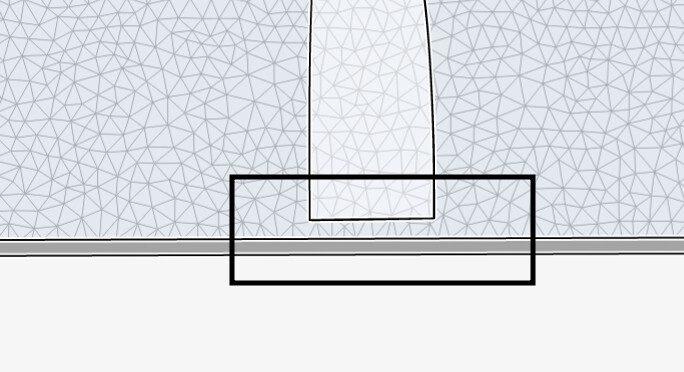
Finally, there is a gap in the root of the wing, close to the boundary. May I ask why?
I hope this helps,
Best regards,
J.A. Gutiérrez
1 Like
I changed my simulation setup now, but the velocity magnitude is still increasing. The space between BC and Wing simulates the distance between the wingsail and water surface.
Do you have any other tips how I can adjust my setup for realistic values ?
Kindly, let me know what you changed, ie:
- Potential flow initialization,
- etc…
- BC custom set to Freestream
- enabled potential flow initialization
- initial Condition, stream set to 5.4 m/s Ux
1 Like
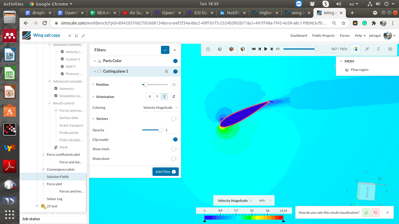
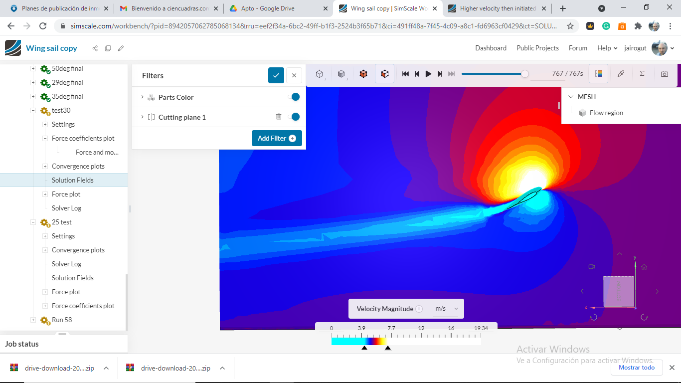
I’ve checked the last two cases you stopped (25 and 30 deg) and they don’t seem to have any issues, you have a nice velocity contour:
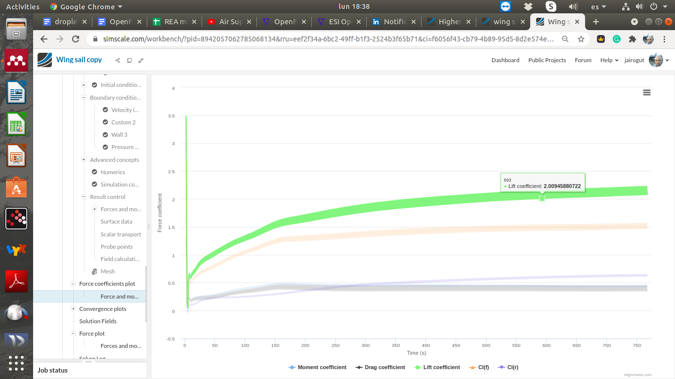
Here you have a nicely converging Cl graph:
And nice semi-converged resiudals:
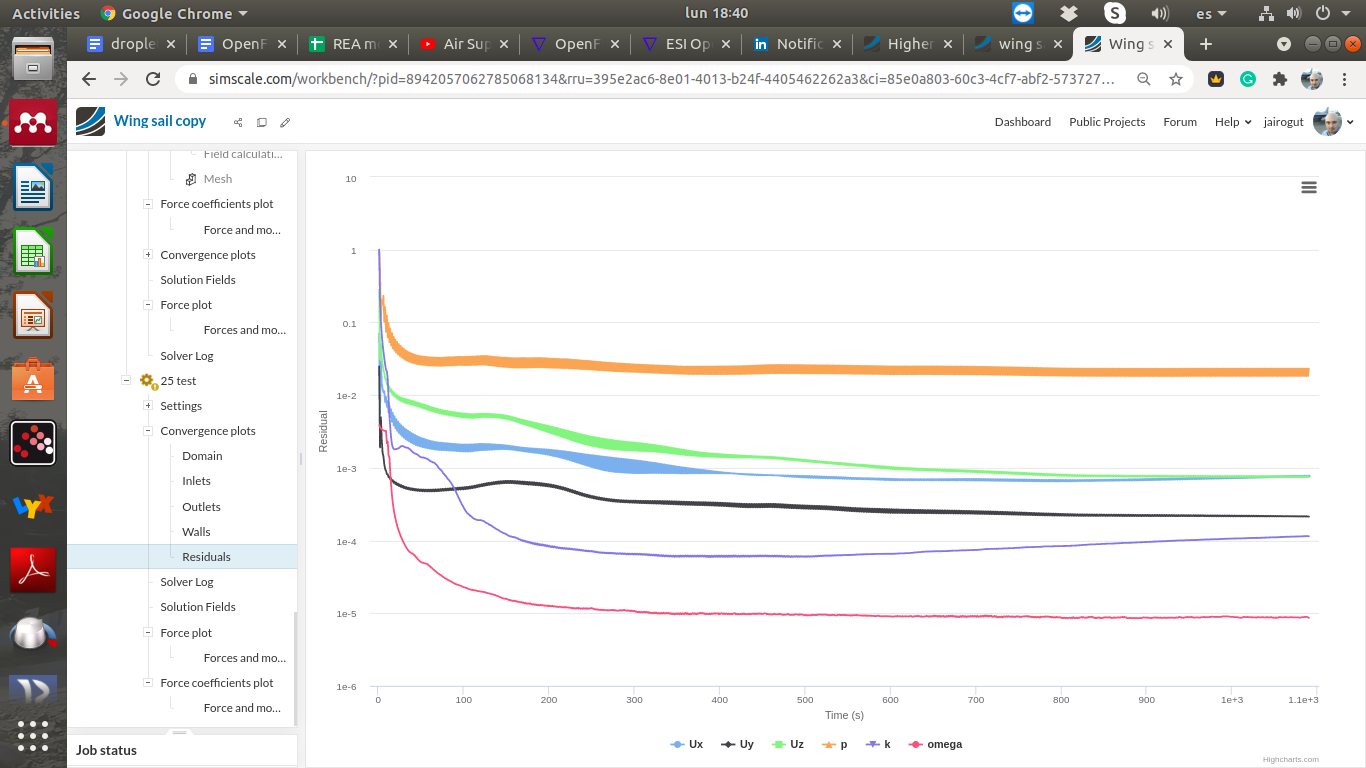
Pressure will not converge below this value because the flow is unsteady in the wake of the wing.
So, what is troubling you?
1 Like
Two things are troubling me.
-
As you can see in your screenshot, the velocity in the enclosure is about 8 m/s, while I have set an velocity inlet speed of 5,4 m/s. Meaning that the lift forces that I want to measure for 5,4 m/s are not accurate.
-
The force curves are very thick with values jumping about 500 N sometimes.
I am slowly running out of time. I need these values for my thesis which is due soon. I Hope that you can assist me a little bit more.
Hi, the velocity inside the domain is correct. You can´t tell the exact value from a low-contrast contour plot (using a beta version). You need to use probes or modify the range/contrast of the contour. I am posting an example:
Whereas the thickness of a force curve, you need to understand the nature of a CFD simulation. The value goes up and down every iteration (making it look thick). You are simulating a high AOA using a steady state solver. I’m not going to do your homework, but it is clearly related to that and may part of your thesis discussion. (just a piece of advice: go and check the force graphs at low AOA and verify if they are also “thick”) The lift coefficient is logical and expected, therefore so are the force values (which are used to calculate the lift) The results are the ones you would expect for a RANS simulation at a high AOA.
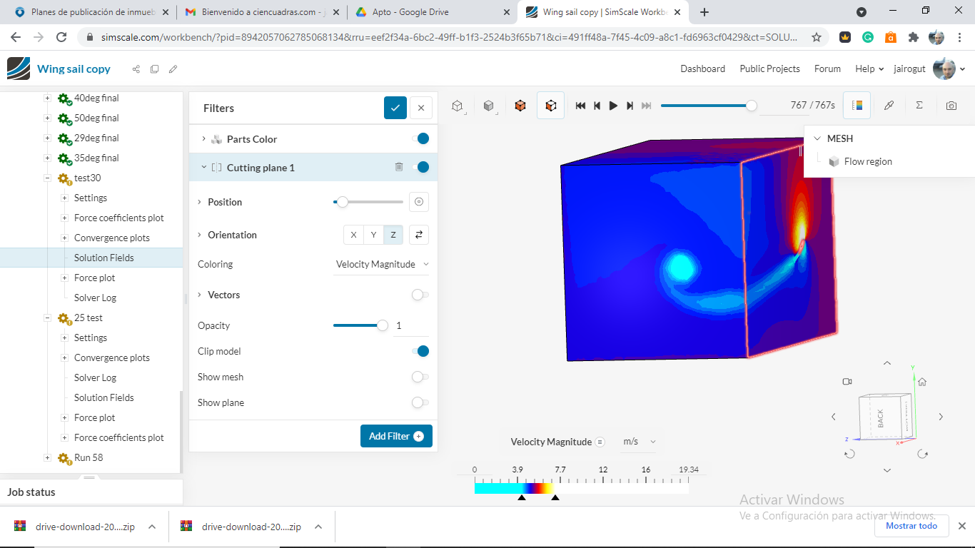
Final tip: The contour I uploaded shows the domain should have been a bit longer downstream, as you see, at the outlet, the wake is still observed. It does not mean you have to start all over (as you have no time) but it is a useful piece of advice to write in your discussion. The same happens for the height of the domain, and the wingtip vortex trail as this picture shows:
1 Like
Okay understood. Actually this part makes about 2% of my Thesis. I thought that the thick curves occurs at high AOA due to the stall at the wing tip and aft end. So I tried an AOA of 10, but the same thick curve appears. I also widened the enclosure and now I do not have any changes of velocity at the borders of the enclosure, which I think is good.
1 Like
Stall is a transient process which cannot be completely captured by a steady-solver. The movement up and down in the force plot is a consequence of the sovler struggling to find a steady state solution where it does not exists. (still you will get a very good cost-effective approximation)
1 Like
So would you recommend doing a transient simulation for one AOA ?
That depends on your project objectives. In CFD, it is always possible to improve the accuracy of the results at the expense of a very large increase in the computational costs. A transient simulation will be much more costly and if you don’t have, for example, buffeting or flow separation control among your thesis objectives, it might not be worth expending resources on it.